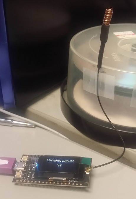
I have attached my current sample code to send and receive. It makes use of the Arduino LoRa Library by Sandeep Mistry and displays RSSI and SNR of the received data.
The very versatile RadioHead RF95 Library also works now without additional tweaks! You need at least version 1.80. Prior versions failed to compile (missing atomic.h).
Since these modules don't have a tcxo, there is a slight frequency mismatch. RadioHeads 'frequencyError()' tells me, the relative offset between my modules to be roughly approx. 1.5kHz.
[2018-06-06] cool new Products:
Now this is a complete solution for a standalone GPS-Tracker based on LoRa:
TTGO T-Beam ESP32, LoRa with NEO-6M GPS and 18650 Battery holder
The module now also offers a dedicated ON/OFF Button. An external GPS Antenna is attached via U-FL and the LoRa Module now has an SMA Connector for the Antenna. Just keep in mind that this device does not come with an OLED display!
[03.03.2018] new Case on thingiverse:
A nice new case for the TTGO ESP LoRa OLED V2 module just popped up on thingiverse, published by [decoder]. In case you were not aware, V2 is the new version with the USB-port rotated by 90° apart on the wide side. From the case you have access to the Reset button, power on/of and on the SD Card slot.. The case also offers space for a small LiPo battery.
Check it out and send us your picture in case you have it printed!
[05.02.2018] Product update:
TTGO just recently released an upgrade to their popular LoRA Modules, referred to as V2.0. This board is supposed to be superior in design for both bands (433MHz and 868/915MHz).
New features include:
- microSD-Card Slot
- USB Port moved to the side
- shielded SX127x RF section
- new positioned WiFi antenna (the previous version sufferd from a poor design!)
- battery switch
Check out the V2.0 series at http://s.click.aliexpress.com/e/vB2rnmu
--
product update: TTGO finally offers a 3d printed case/shell for the ESP32 Lora Module. Available in black or white.
good news: 868MHz (EU) / 915MHz (US) Version now avaliable on Aliexpress
--
[update]
A new case design by [klkl] just (November, 26.) popped up on thingiverse:
https://www.thingiverse.com/thing:2670713
Not sure if that one has enough space for a LiPo Battery beneath the module. Since it's tagged 'work in progress', details and features might yet be optimized...
--
There's a nice case created by Aleksei Golikov / lexgol for the heltec Wifi LoRa 32 board: https://makerware.thingiverse.com/thing:2581459
Just download the files and have it printed yourself.


 Blecky
 Varadi, Gyorgy aka bodri
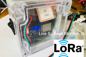
 K Gray
 DrYerzinia
For battery voltage measurement on the Heltec boards, use GPIO 13 or 37 depending on the version of the board you have. All of the boards I've bought on Amazon were version 2.1 with battery voltage on GPIO 37 and based on my experimentation, you'll get a reading on that pin with or without a battery as long as the board is powered (without a battery, I'm assuming the voltage is the output of the charging circuit).