 modder_mike
After @kevtris posted the image of the font hidden in the image file, I thought it might be fun to poke around in there some more and see what could be seen. I started by mapping out the following data areas (defined as "long" stretches of bytes other than 0xFF):
0x000000-0x000003: FF FF FF FF (4 bytes)
0x000004-0x029503: FPGA boot bitstream (169216 bytes)
0x030002-0x03D407: Something (54278 bytes)
0x040000-0x0400BB: Something (188 bytes)
0x09006C-0x0A3513: Something (79016 bytes)
0x0B0000-0x0B004B: Something (76 bytes)
0x0D6AFC-0x113513: Something (248344 bytes)
0x120000-0x1200D7: Something (216 bytes)
0x1400B8-0x141B05: Something (6734 bytes)
0x142B00-0x144605: Something (6918 bytes)
0x145600-0x147105: Something (6918 bytes)
0x150000-0x1500A7: Something (168 bytes)
There are three large blocks of data, and in each area can be found a copy of the font that @kevtris documented. Presumably these are firmware images.
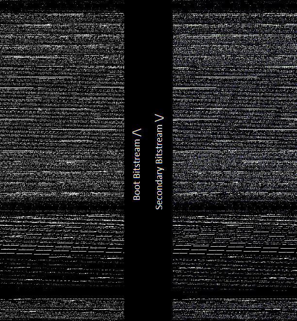
The font was found with bit spatial analysis (a term I'm using because I don't know the proper term for this) using yy-chr. That got me thinking, what else might we figure out by looking at the dumped image visually? So I mangled the data a bit and came out with the following grayscale representation:

Interesting. If we know the first band at the top is the FPGA's boot bitstream... then the band in the middle sure looks like another one - but upside down. The data seems to back this up - starting at 0xFFFFF and continuing backward to 0xD6AFC, there seems to be another 169220 bytes of bitstream there. I ran a diff between the two bitstreams, and though they look similar, about half of the bytes are different - and since most of the bitstream is zeros, that means there are a whole lot of differences. But they are both undoubtedly the same type of data:
With that chunk removed from the 248K of continuous data noted above, we end up with 79124 bytes - much closer in size to the other two similar-looking sections. Given this, the presence of the font in all three places, as well as a set of strings in all three, it seems that the flash contains two bitstreams, three firmwares, and some small chunks of other data interspersed here and there. Neat!
[Edit] Addendum. The reversed bitstream is a documented feature of Spartan-3E. It is part of its MultiBoot function. On first powerup, the FPGA loads a bitstream starting either at the bottom of its address range and reading up, or from the top of its address range and reading down, depending on the configuration of the bitstream header. Then once this is loaded, by toggling the FPGA's MultiBoot Trigger signal, the FPGA is instructed to reconfigure itself from the opposite end of the memory in reverse order. Except as you see here, the second image is at 0x0FFFFF, which is not the end of the flash address space, so the programmer seems to have done something interesting with the memory architecture. It is possible that the flash configurator (iMPACT or similar) was configured for a 1M flash, and the programmer appended additional data after the end of the MultiBoot bitstream, because I can't otherwise figure out how to get iMPACT to override the start address for the second image...
The dual bitstream function is often used as a safety feature for field-upgradeable systems. One of the two is protected, and the other is allowed to be written by user software. If the upgrade goes poorly, there is always a known-good bitstream to bring up the FPGA so that it can be attempted again, and you don't have to go find the JTAG cable. Another neat feature that Barco may have taken advantage of.
Discussions
Become a Hackaday.io Member
Create an account to leave a comment. Already have an account? Log In.
This is really cool. Have you tried the different data entropy tools? They show stuff like this. I was playing with this and the data off the i2c EEPROM data, but I didn't get this far. In particular, I really enjoy using Veles: https://codisec.com/veles/ They have good 2d visualization, as well as 3d (although I find the 3D representation was only useful for image data).
Are you sure? yes | no
Hmm, interesting. I've never run across Veles before. I did try running the raw dump through binwalk, which didn't seem to know what to do with the mostly empty image containing multiple independent firmwares and bitstreams. Then again I'm really a newbie at this, so maybe someone more seasoned at binary reverse engineering would have an easier time :)
Are you sure? yes | no
Ha very interesting finding different fw in there. Nice. Given that there's (almost) certainly a CPU in there (micro/picoblaze) one wonders where it boots from and if there's a disassembler...
Are you sure? yes | no
The organization of the code seems to be in 32-bit chunks, which points to Microblaze if it is one of the two (Picoblaze is 18-bit instructions, if I recall correctly). I'm tearing apart the first 78k firmware right now. The end of the file has eight 256-entry 24-bit brightness correction curves, in addition to the strings and font that were already located. Before the curves appears 67k of data semi-repeating in 32-bit blocks. The regular Microblaze disassembler doesn't know what to do with the data, so I'll probably end up writing a quick and dirty trial disassembler to interpret a few instructions (or maybe do it by hand) and see if they make any sense.
Are you sure? yes | no
re: disassembling the code; I was going to write a disassembler for it but ran into some problems. The data in the flash is bit-reversed it looks (going by documentation and the configuration data's header which is bit reversed according to the documentation). So maybe the bytes need to be bit-reversed before disassembly? The data definitely looks like microblaze though; the upper 11 bits of many instructions at 0's and this seems to be reflected in the data.
Where's the "proper" disassembler? part of the xilinx toolset?
Are you sure? yes | no
I haven't tried it but
/opt/Xilinx/14.7/ISE_DS/EDK/gnu/microblaze/lin/bin/mb-objdump
looks hopeful.
Are you sure? yes | no
@SpaceCoaster: mb-objdump is "the regular Microblaze disassembler" I tried, and it didn't know what to make of the dump.
A Microblaze opcode is 6 bits long. I made a list of all the documented Microblaze opcodes (there are some missing codes), and compared the list against the first six, last six, and reversed first six and last six bits of each byte of each apparent instruction, and all permutations yielded usage of missing codes. I'm not 100% convinced it's a stock Microblaze core.
Are you sure? yes | no