Close
0%
0%

ATTiny9 blinky

Simple project to demonstrate how to implement a blinking LED with an ATTiny and an Arduino as a programmer.

Similar projects worth following

This project shows you how to program an ATTiny9 microcontroller. You need an additional Arduino for this, I tested it with an Arduino Uno, for which the programming script was written. It might work with other Arduinos as well, if you connect it to different pins for SPI, see the connections table here.

This is the circuit diagram, the KiCad files for it are in the files section:

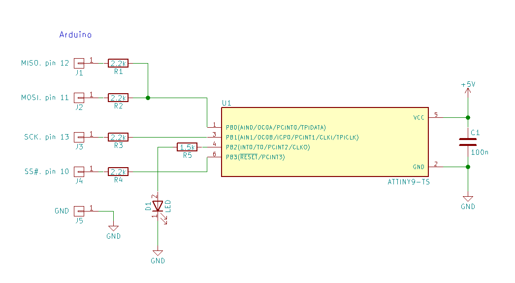
Instead of 2.2k resistors, the programming script says you can use lower values, like 1k resistors, but works with 2.2k as well. And I used an external 5V power supply, but you can use the 5V from the Arduino instead.

You have to connect +5V to pin 6, reset, of the ATTiny9 (or with a resistor), when you disconnect the Arduino programmer.

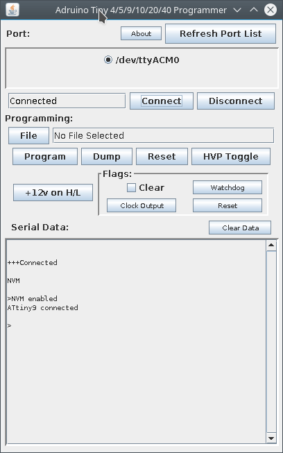
The Arduino is used as a programmer for the ATTiny9, as described in this article. I copied the Arduino script and the Java GUI in the files section of this project. For a first test, just flash the Arduino script, then start the Java GUI like this:

java -jar ATTiny4_5_9_10_20_40_Programmer.jar

Then you can click "Connect" and if the wiring is right, you should see this:

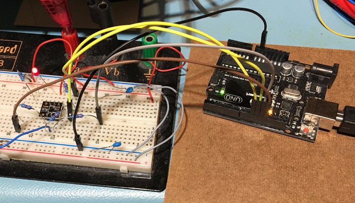
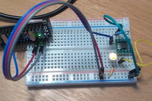
Then you can select the blinky.hex file and click on "Program". It should program the microcontroller and you should see the LED blinking. My test setup:

Closeup of the breakout board:

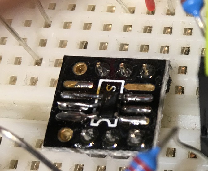
It was not quite the right size, so I used some additional silver wires on one side to solder it.

If you want to write your own programs, first install Atmel Studio. Then follow the steps as explained on my websites, for example this one. After compiling, the resulting HEX file is in the ProjectName/Debug directory. The blinky.hex file in the files section was compiled from the main.c file in the files section.

attiny9-blinky.zip

KiCad files

Zip Archive - 2.59 kB - 10/24/2017 at 03:27

Download

ATTiny4_5_9_10_20_40_Programmer.jar

Java GUI for the Arduino programmer

x-java-archive - 185.44 kB - 10/24/2017 at 02:49

Download

ATtiny4_5_9_10_20_40Programmer.ino

programming script for Arduino Due

x-arduino - 22.86 kB - 10/24/2017 at 02:48

Download

blinky.hex

generated HEX programming file

x-hex - 369.00 bytes - 10/24/2017 at 02:47

Download

main.c

AtmelStudio C file

x-csrc - 256.00 bytes - 10/24/2017 at 02:46

Download

  • clock, delay function, timer interrupt, and PWM

    Frank Buss10/28/2017 at 04:28 3 comments

    The ATtiny9 has an internal oscillator of 8 MHz, which is enabled by default on reset, with a prescaler of 8, resulting in a CPU frequency of 1 MHz. The GNU compiler has a builtin delay function _delay_ms. To use this function, you have to define the CPU frequency with the F_CPU macro and then include util/delay.h. For 1 MHz it can delay up to 4.2 seconds.

    Example for a 1 Hz blinker:

    #define F_CPU 1000000UL
    #include <avr/io.h>
    #include <util/delay.h>
    
    int main(void)
    {
        DDRB |= 1 << PINB2;
        while (1) {
            PORTB &= ~(1 << PINB2);
            _delay_ms(500);
            PORTB |= 1 << PINB2;
            _delay_ms(500);
        }
    }
    

     Internally it uses delay loops, so you can still do other things with the internal timers. 

    The accuracy of the 8 MHz oscillator is guaranteed to be within +/-10% with factory calibration, says the full datasheet, see chapter 17.4.1. Accuracy of Calibrated Internal Oscillator. It can be calibrated to +/-1% manually with the OSCCAL value. Unlike with the PIC microcontrollers, looks like the IDE has no integrated support to do the calibration and to save it in a protected flash location, but there are instructions how to do it, like this one. When I tested it at 20°C room temperature and with 5V power supply, the factory calibration was already better than 1%.

    The _delay_ms function uses a delay loop, which has some disadvantages, e.g. if you need an exact time interval, you have to adjust the delay value depending on the rest of the program. 

    A better way to do the delay is by using a timer. The following program uses the 16 bit Timer0 and the capture compare functionality to generate an 1 kHz interrupt. The CPU clock is also changed to 8 MHz, so that you can do more things in the interrupt, if necessary:

    #include <avr/io.h>
    #include <avr/interrupt.h>
    #include <stdint.h>
    
    volatile static uint16_t millis = 0;
    
    // interrupt for compare match
    SIGNAL (TIM0_COMPA_vect)
    {
        if (millis < 500) {
            PORTB &= ~(1 << PINB2);
        } else {
            PORTB |= 1 << PINB2;
        }
        millis++;
        if (millis == 1000) millis = 0;
    }
    
    int main(void)
    {
        // unprotect the CLKPSR register
        CCP = 0xd8;
    
        // set prescaler to 1 for 8 MHz CPU clock
        CLKPSR = 0;
    
        // configure pin B2 as output
        DDRB |= 1 << PINB2;
        
        // count up to 1000 for 1 kHz interrupts
        OCR0A = 1000;
    
        // clear timer on compare match (CTC) mode
        // clock source clk/8
        TCCR0A = 0;
        TCCR0B = (1 << WGM02) | (1 << CS01);
    
        // enable interrupt on OCR0A match
        TIMSK0 = 1 << OCF0A;
    
        // clear all interrupt flags
        TIFR0 = 0xff;
    
        // global interrupt enable
        sei();              
        
        // the rest is done in the interrupt
        while(1) {
        }
    }
    

    This needs about 3 mA (without the LED connected).

    Finally you can use the PWM output for the blinking LED. For this connect it to PB0 and use this code:

    #include <avr/io.h>
    #include <avr/sleep.h>
    
    int main(void)
    {
        // unprotect the CLKPSR register
        CCP = 0xd8;
    
        // set prescaler to 1 for 8 MHz CPU clock
        CLKPSR = 0;
    
        // configure pin B0 as output
        DDRB |= 1 << DDB0;
    
        // 1 HZ PWM frequency (8 MHz / 1024 / 2 - 1)
        OCR0A = 3905;
    
        // toggle OC0A on compare match
        // clear timer on compare match (CTC) mode
        // clock source clk/1024
        TCCR0A = 1 << COM0A0;
        TCCR0B = (1 << WGM02) | (1 << CS00) | (1 << CS02);
    
        // go to sleep for the CPU
        set_sleep_mode(SLEEP_MODE_IDLE);
        sleep_enable();
        sleep_mode();
    }
    

    Enabling the sleep mode at the end reduces the power consumption to about 1.3 mA (without the LED).

    With a different prescaler this could be used as a simple high resolution, fixed frequency square wave generator. For example 1 kHz:

    #include <avr/io.h>
    #include <avr/sleep.h>
    
    int main(void)
    {
        // unprotect the CLKPSR register
        CCP = 0xd8;
    
        // set prescaler to 1 for 8 MHz CPU clock
        CLKPSR = 0;
    
        // configure pin B0 as output
        DDRB |= 1 << DDB0;
    
        // 1 kHZ PWM frequency (8 MHz / 2 / 1000 - 1)
        OCR0A = 3999;
    
        // toggle OC0A on compare match
        // clear timer on compare match (CTC) mode
        // clock source clk/1 (no prescaler)
        TCCR0A = 1 << COM0A0;
     TCCR0B = (...
    Read more »

View project log

Enjoy this project?

Share

Discussions

Similar Projects

Does this project spark your interest?

Become a member to follow this project and never miss any updates