0%
0%
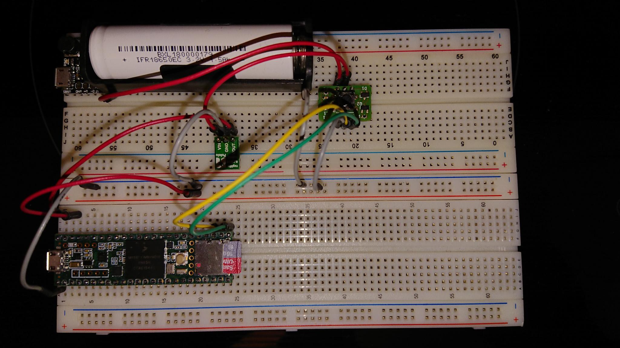
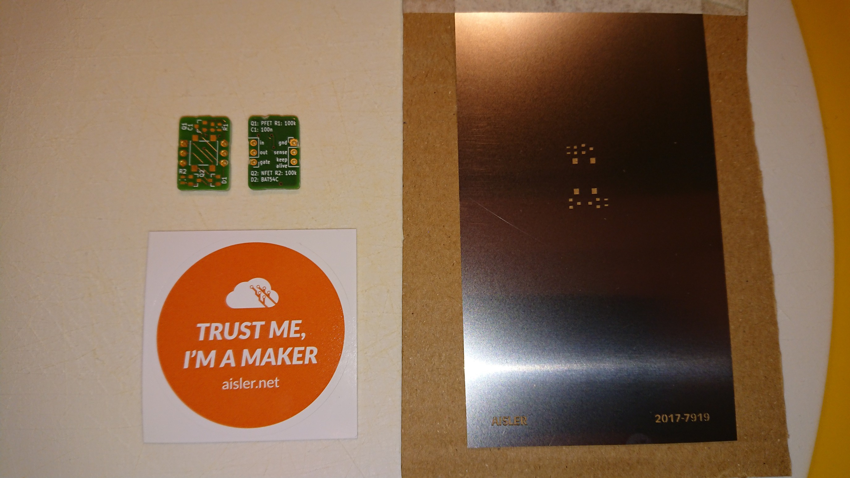
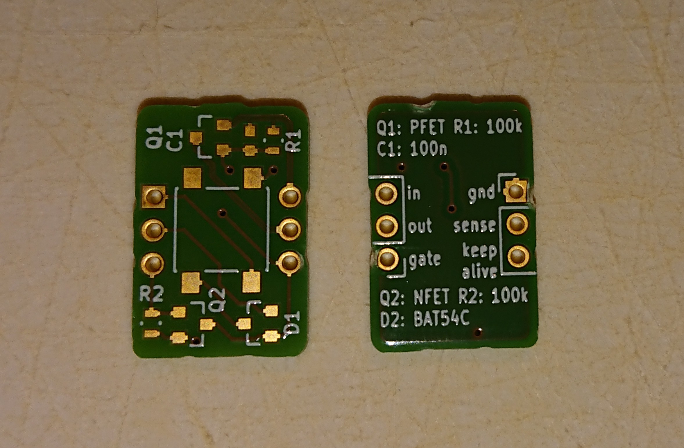
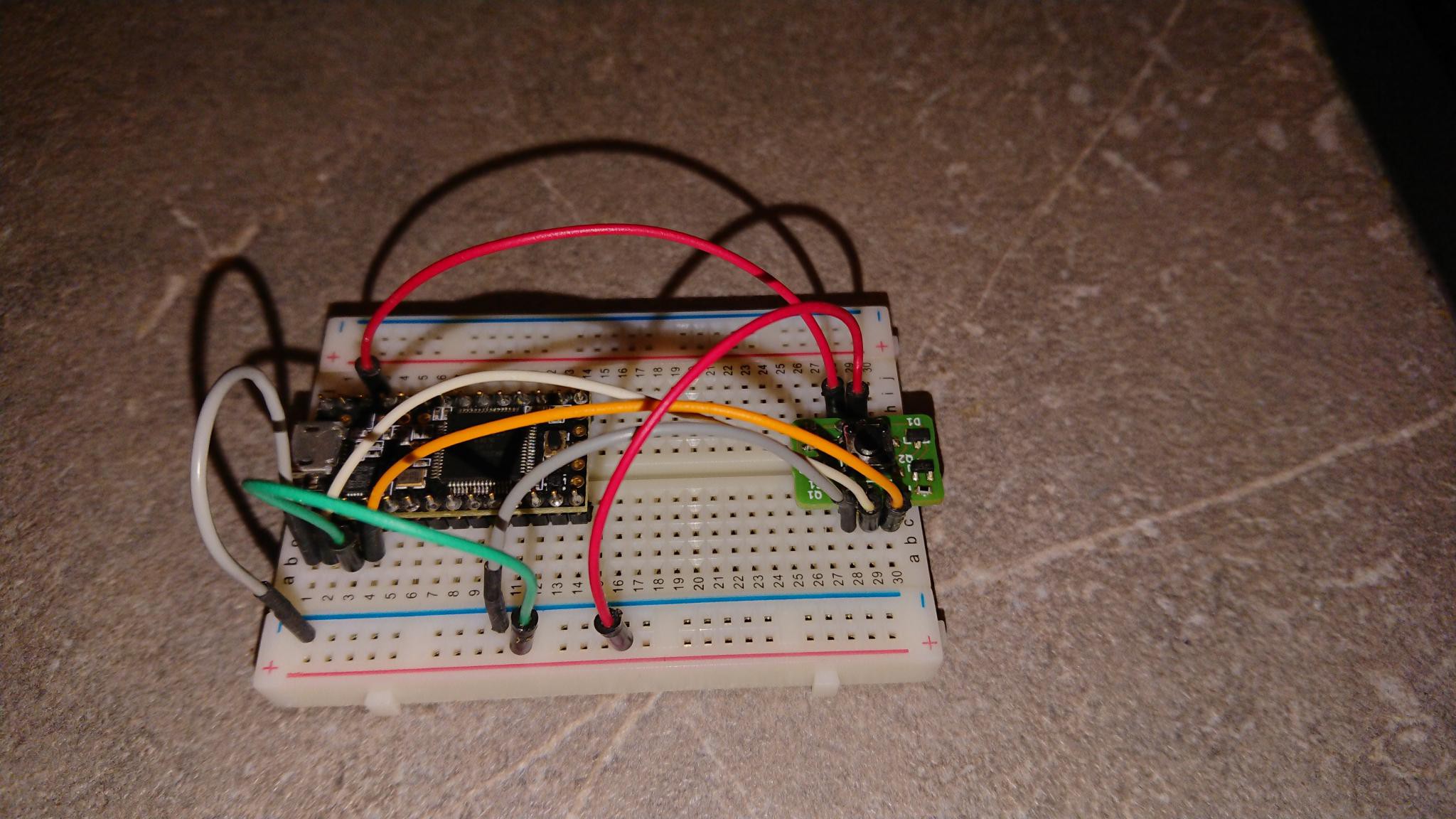
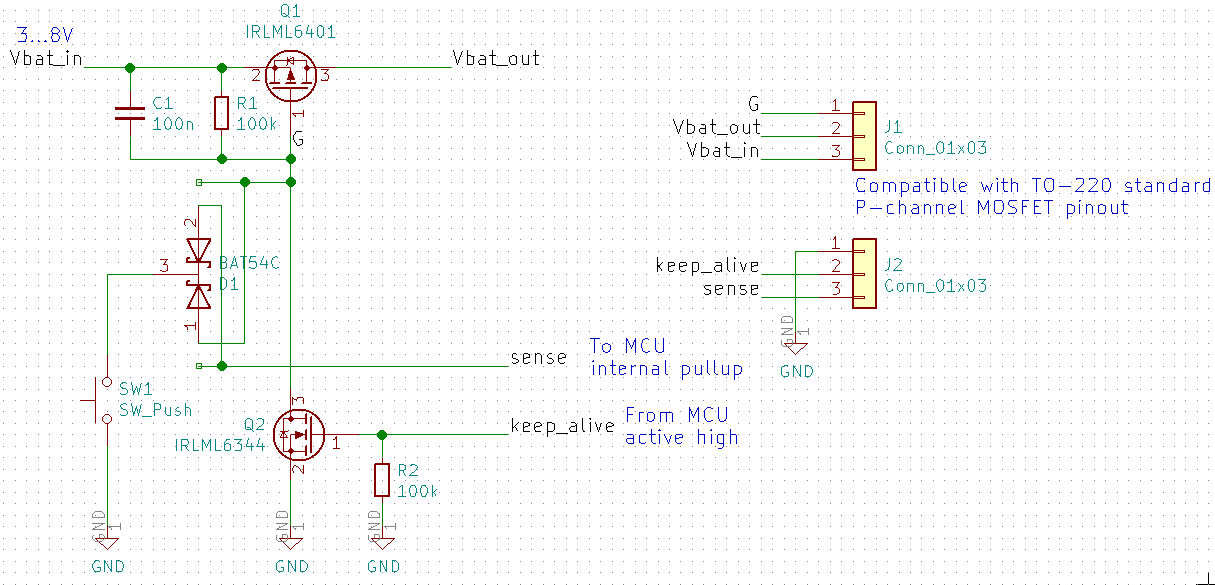
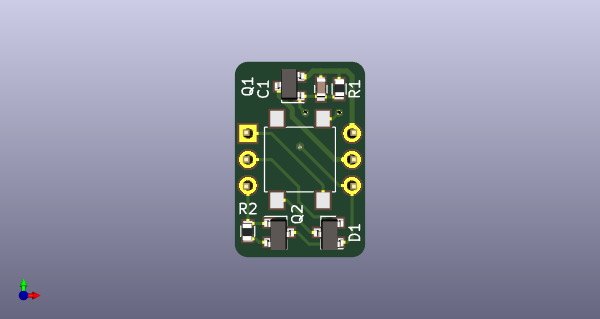
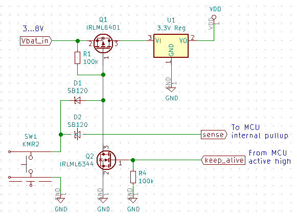
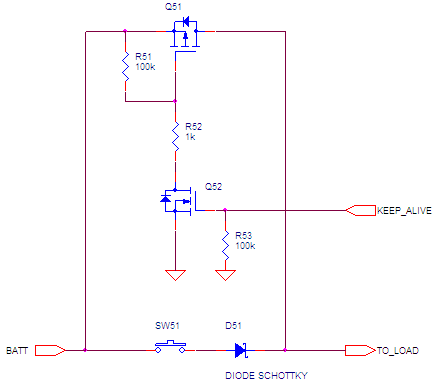
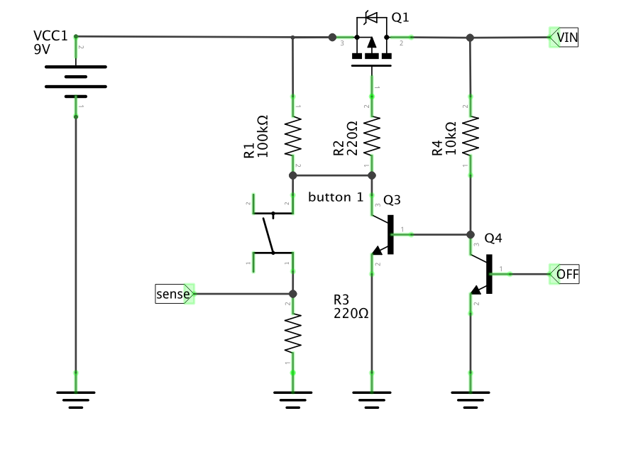
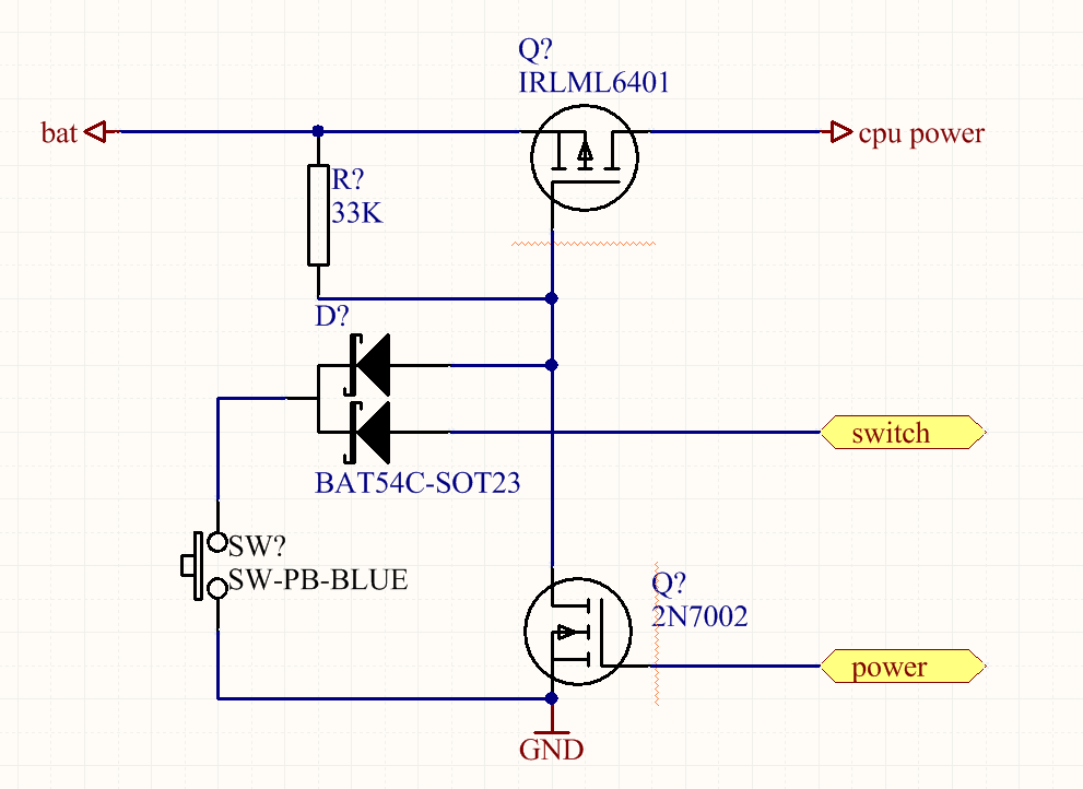
Soft power button with sense output
One of my designs needs a soft power button with sense output. I'm posting my design here to be reviewed and improved.
 Christoph
Become a Hackaday.io member
Already have an account? Log in.
Just one more thing
To make the experience fit your profile, pick a username and tell us what interests you.
Pick an awesome username
hackaday.io/
Your profile's URL: hackaday.io/username. Max 25 alphanumeric characters.
Pick a few interests
Projects that share your interests
People that share your interests

 Nick Sayer
 Jay Riedl
 Yann Guidon / YGDES
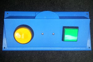
Great project! I like the idea of using only standard components which makes the design more adaptable. For the people looking for the most compact (and expansive) solution, the MAX16054 may be a good option (this is just for inspiration, not as replacement for your project). Thx again!