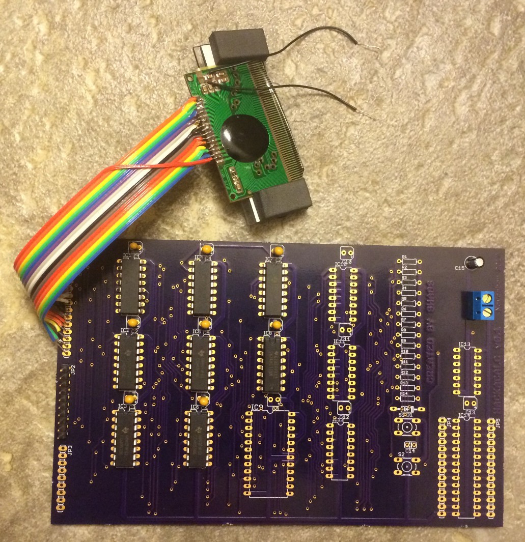
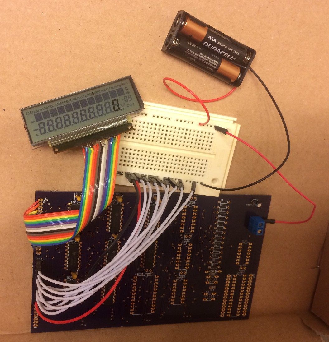
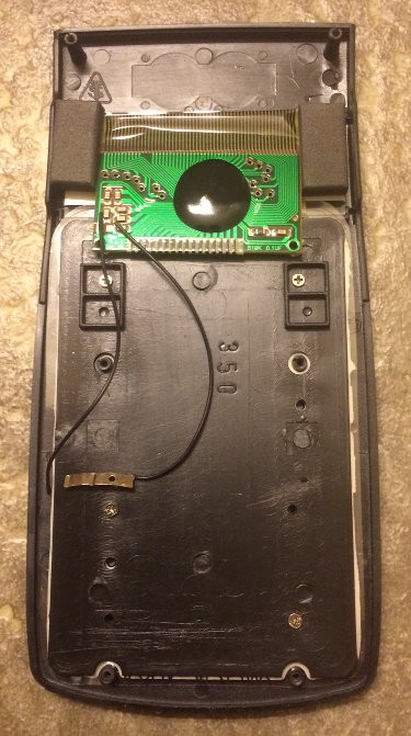
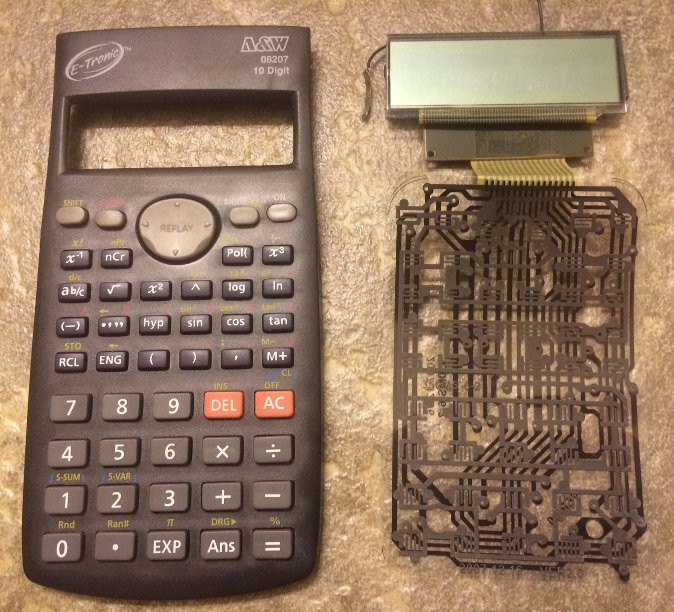
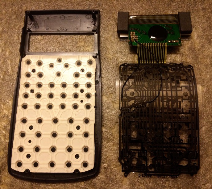
Close
0%
0%

HACKACALC

Under this project I will document a process of converting cheap scientific calculator into cool programmable one :)

Similar projects worth following
I'm one of the millions of people who grew up with programmable calculator as their only "computer", which taught us to code even before we saw a real computer, and now programmable calculators are mostly relic and even some still available in stores, they are a little bit too expensive (as HP-12C for example). So I choose non-programmable calculator CASIO fx-82ms (more precisely its clone) to make it programmable by adding additional DIY circuitry. Idea is to connect stepping circuit instead of buttons to the calculator to perform some "program" that is stored into ROM by emulating of pressing buttons of the calc. This calc by itself is pretty sophisticated - it has 2 line display (79-character entry line and 10-digit result line with optional 2-digit exponent), 9 variables (M,X,Y,A,B,C,D,E,F) and capability to perform statistical and regression computations! "Noname" clones of such calculator is available for under $10.

Phase 1: add stepper circuit to the calc to perform some "program" by simulating keypresses

Phase 2: add unconditional jumps to pages (128 bytes each)

Phase 3: add unconditional jumps in boundaries of current page (opcodes 0x80...0xFF)

Phase 4: add feedback through LCD to make conditional jumps (skip-if), implement subroutines

Phase 5: add decoder ROM to enable support for multiple brand and clone models

Phase 6: create special programming language and compiler

Phase 7: make a product :)

hackacalc0.zip

Eagle files and Gerbers for prototype v0.1

x-zip-compressed - 570.80 kB - 12/19/2017 at 06:56

Download

calc.png

Image file describing keyboard matrix

Portable Network Graphics (PNG) - 13.26 kB - 10/31/2017 at 04:24

Preview
Download

calc.ods

LibreOffice file describing keyboard matrix

spreadsheet - 12.90 kB - 10/31/2017 at 04:24

Download

  • Frankencalc :)

    SHAOS12/19/2017 at 06:48 0 comments

    I partially assembled the board - only 7 CD4051 and one 74HC138 were populated. Then I removed transparent keyboard circuit from calculator remains and soldered 15 wires to his "brain":

    Added 2xAAA power source (3V) and magic - it worked :)

    I even changed code a little on JP2 inputs and it printed something ;)

    So it looks like it is right direction for further experiments...

    P.S. Just uploaded Eagle files (with Gerbers) to the project

  • Boards received

    SHAOS12/05/2017 at 04:57 0 comments

    Thank you, OSHPark!

    Now I need to perform 1st experiment - keypress simulation :)

  • Prototype v0.1

    SHAOS11/15/2017 at 05:14 0 comments

    I was thinking for so long how I should make my 1st prototype - on breadboard, as wire-wrap assembly or dead-bug style soldering, but finally I've decided to go with PCB (will order through OSHPark as usual) designed in Eagle v5 (version that I have standard license for). So main part of the prototype is 7 analog switches 8:1 (CD4051) and one decoder 3->8 (74HC138):

    Switches implement keyboard matrix 7x8. Also you can see here 2K ROM that will store "program". Additional circuitry is address counter (I'm not so sure that it will work right away):

    And this is manually routed PCB 18x10cm that I will order tomorrow:

    Circuit doesn't have clock generator on board because I didn't decide yet how to do that - most likely here it will be manual step button (with RS-trigger) on prototyping area at the bottom. Will see how it goes...


    UPDATE: Ordered on Nov-16 through OSHPark:

  • Reproducibility-3

    SHAOS11/14/2017 at 08:54 0 comments

    Ok, I've got CASIO fx-350MS:

    it looks exactly the same as all other calcs:

    but inside it's more like fx-82ms:

    it means for now we will use "A&W" clone with flexible keyboard circuit exclusively (at least for some time).

  • Reproducibility-2

    SHAOS11/11/2017 at 07:39 0 comments

    OK, lets take EXACTLY THE SAME model of clone - A&W 08207:

    and it's... DIFFERENT from other A&W 08207 that I use here!

    PCB looks different, number of signal that go to keyboard is different (18 vs 16):

    So still no reproducibility yet, but PCB has name on it and it's 350ms (even though flexible circuit says 82MS-9R) - so it might be clone of CASIO fx-350ms (that should have the same face as well)? Stay tuned to find out...

    P.S. It looks like 2 additional contacts on the left is RESET (in the center on the back), but in the same time other 16 contacts connected to keyboard matrix very differently!

  • Reproducibility

    SHAOS11/11/2017 at 07:29 0 comments

    Lets check other calculators with the same face - just in case somebody will need to independently reproduce this project - CASIO fx-82ms, CASIO fx-300ms and "NONAME" from Amazon for $7.99:

    Without packaging they look exactly the same (except for solar cell on fx-300ms):

    1st one is fx-82ms that looks DIFFERENT from inside:

    2nd one is fx-300ms that looks similar to fx-82ms, but with 1 button battery instead of 1 AA and solar cell:

    3rd one is "NONAME" that is DIFFERENT from originals and from previously opened clone:

    Interesting observation: clones use 2 batteries while originals use only 1 (AA or button).

    So no reproducibility yet...

  • Tracing Keyboard Matrix

    SHAOS10/31/2017 at 03:41 0 comments

    OK, now we can take closer look at transparent keyboard circuitry and trace it by index finger :)

    Green PCB connected to keyboard by 16-signal bus - we can enumerate signals from 1 (left) to 16 (right) and last one is not connected anywhere. After one night of insomnia I've got this matrix (what should be connected to what in order to simulate keypressing):

    It could be directly used as a base for our instruction set - just rename 15 to 0 and we can take columns as higher nibble of opcode and rows as lower nibble of opcode, so ON would be 0x67; A=1 would be 0x48 (1), 0x6E (SHIFT), 0x4E (STO), 0x3E (A) and so on. Rest of the codes could be used for future branching, looping, comparison etc.

    P.S. CASIO fx-82ms manual can be downloaded from here

  • Scientific Calculator

    SHAOS10/30/2017 at 06:26 2 comments

    Chosen NON-programmable scientific calculator is clone of CASIO fx-82ms:

    While original CASIO fx-82ms costs $12 (see here), "noname" clone is available for $7.99 (see here).

    Inside of the calculator we see a small green PCB with on-board chip under black compound:

    In this particular model a keyboard circuit is located on transparent flexible "board":

View all 8 project logs

Enjoy this project?

Share

Discussions

zpekic wrote 11/07/2023 at 00:49 point

Hi, did you consider using a cross-bar switch to emulate the keyboard? Essentially instead of matrix connection done through the keyboard, it is done by flipping a bit in the MT8816 (or similar) memory. I have seen clever adapters from new USB based keyboards to connect to motherboards of home computers, in this case the program would "type" the keystrokes. Check out my bit-serial CPU for example of MT8816 use, quite an interesting chip. 

  Are you sure? yes | no

zpekic wrote 11/07/2023 at 02:59 point

Of course, CD4051 is the retro IC with similar function, but with a slightly more modern version 1 MTxxxx and 1 MCU would be all needed to "automate" many different calculators. 

  Are you sure? yes | no

SHAOS wrote 11/07/2023 at 05:15 point

OK, thanks - I'll check this out

  Are you sure? yes | no

Ken Yap wrote 11/07/2023 at 05:28 point

Another way is to sync to the column outputs and pull up the key detect line when that column should be "connected" to the input "by switch". Probably suffices to detect the leading edge of the first column, measure the time of the whole cycle and use the appropriate time slot for a given column.

  Are you sure? yes | no

super.zizo.mum wrote 10/27/2023 at 07:09 point

please i need help

  Are you sure? yes | no

super.zizo.mum wrote 10/27/2023 at 07:09 point

soooo how do i do that i dont understand most of that...

  Are you sure? yes | no

jaromir.sukuba wrote 11/18/2017 at 15:05 point

Interesting project. So, basically, you are building CPU based on calculator, where the calculator is used as ALU? Oh, that's so lovely sick :-)

  Are you sure? yes | no

SHAOS wrote 11/18/2017 at 15:20 point

Not exactly - human is still entering data into variables and then reading results from the screen. At least for this phase - may be later when I'll do feedback through screen the calculator brain might be used as true (kind of) CPU :)

  Are you sure? yes | no

Jarrett wrote 10/30/2017 at 16:31 point

Wow, there's really nothing in that

  Are you sure? yes | no

SHAOS wrote 10/30/2017 at 23:11 point

Really nothing in this project or really nothing in this calculator? ;)

  Are you sure? yes | no

Jarrett wrote 10/30/2017 at 23:15 point

The calculator! It's mostly free air

  Are you sure? yes | no

SHAOS wrote 10/30/2017 at 23:18 point

It's mostly buttons :)

  Are you sure? yes | no

Similar Projects

Does this project spark your interest?

Become a member to follow this project and never miss any updates