Kirschner Christoph
1. Building a prototype:
The first step was to designe a small PCB with capacitive buttons on it and to mill it with my othermill, to check out how easy or hard it would get to read out the buttons with an atmega32u4 aka an arduino pro micro aka an arduino leonardo board.
This first test was quite successfull and I was able to controll the volume of my laptop very easyly.
2. Test the test-circuit with an phone:
Because I bought the Fairphone recently and it didn`t arrive jet, I had to test it with an other mobile phone (with usb otg). This worked also quite well and so ...
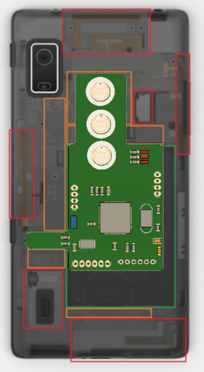
3. The real PCB for the Fairphone:
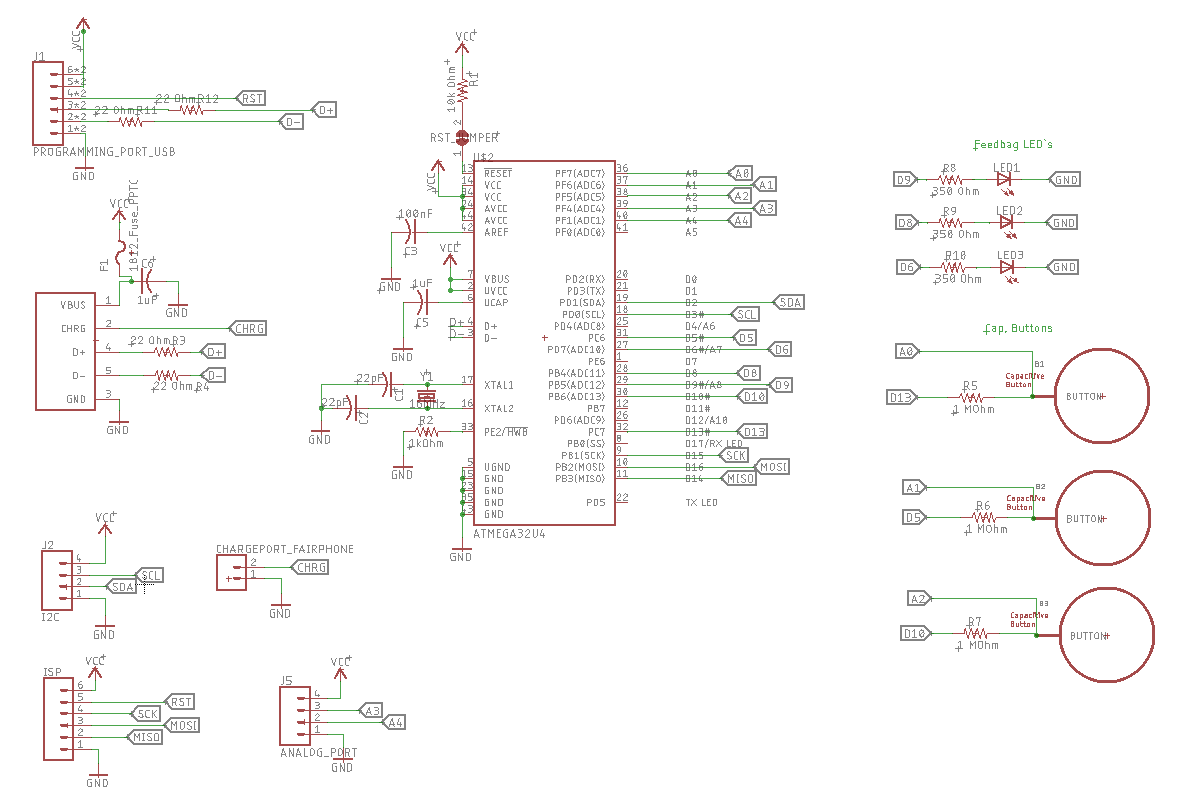
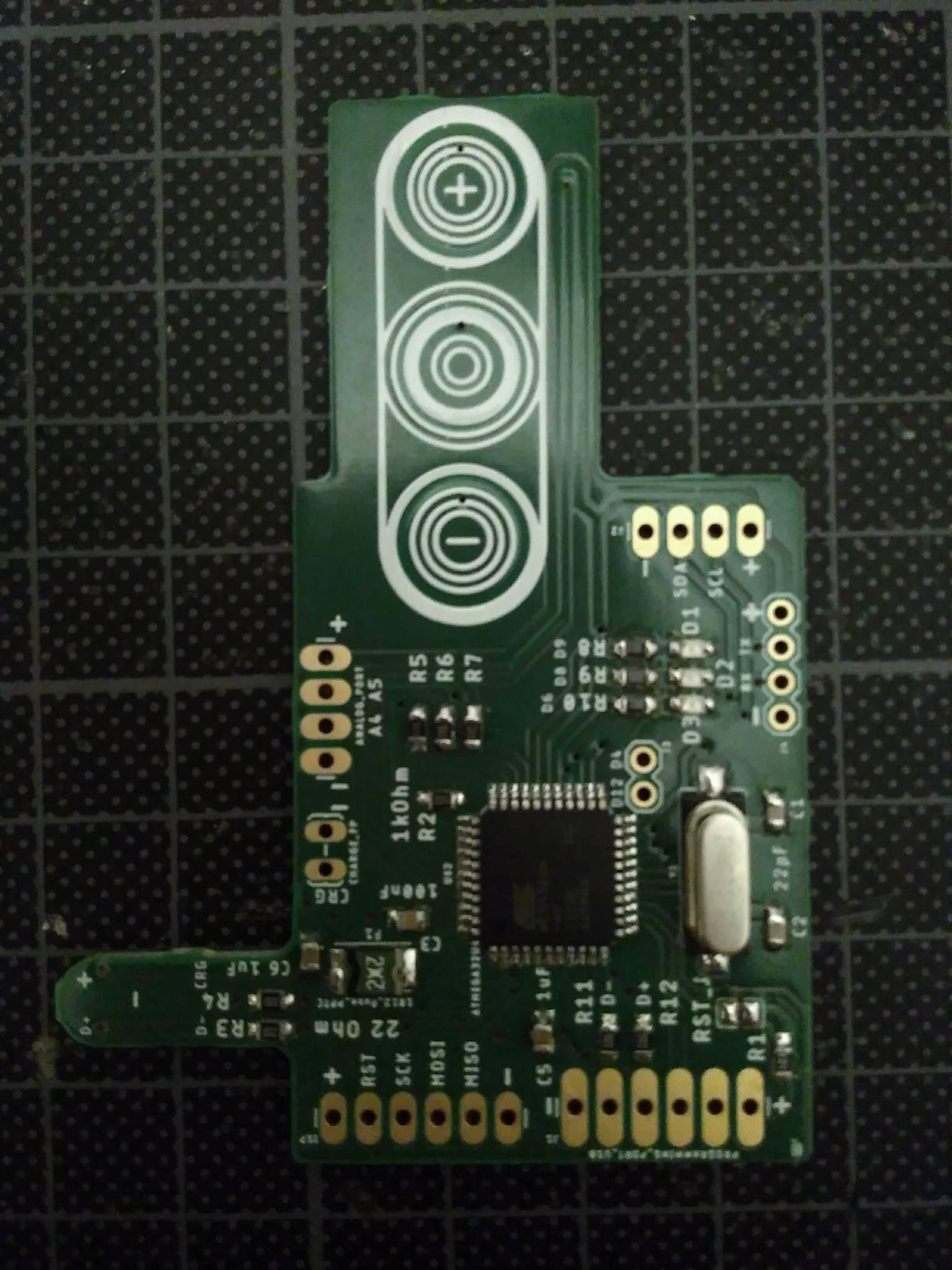
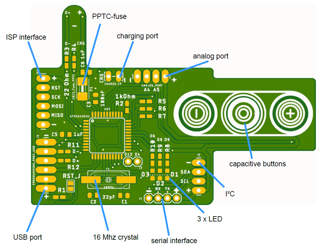
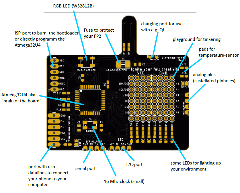
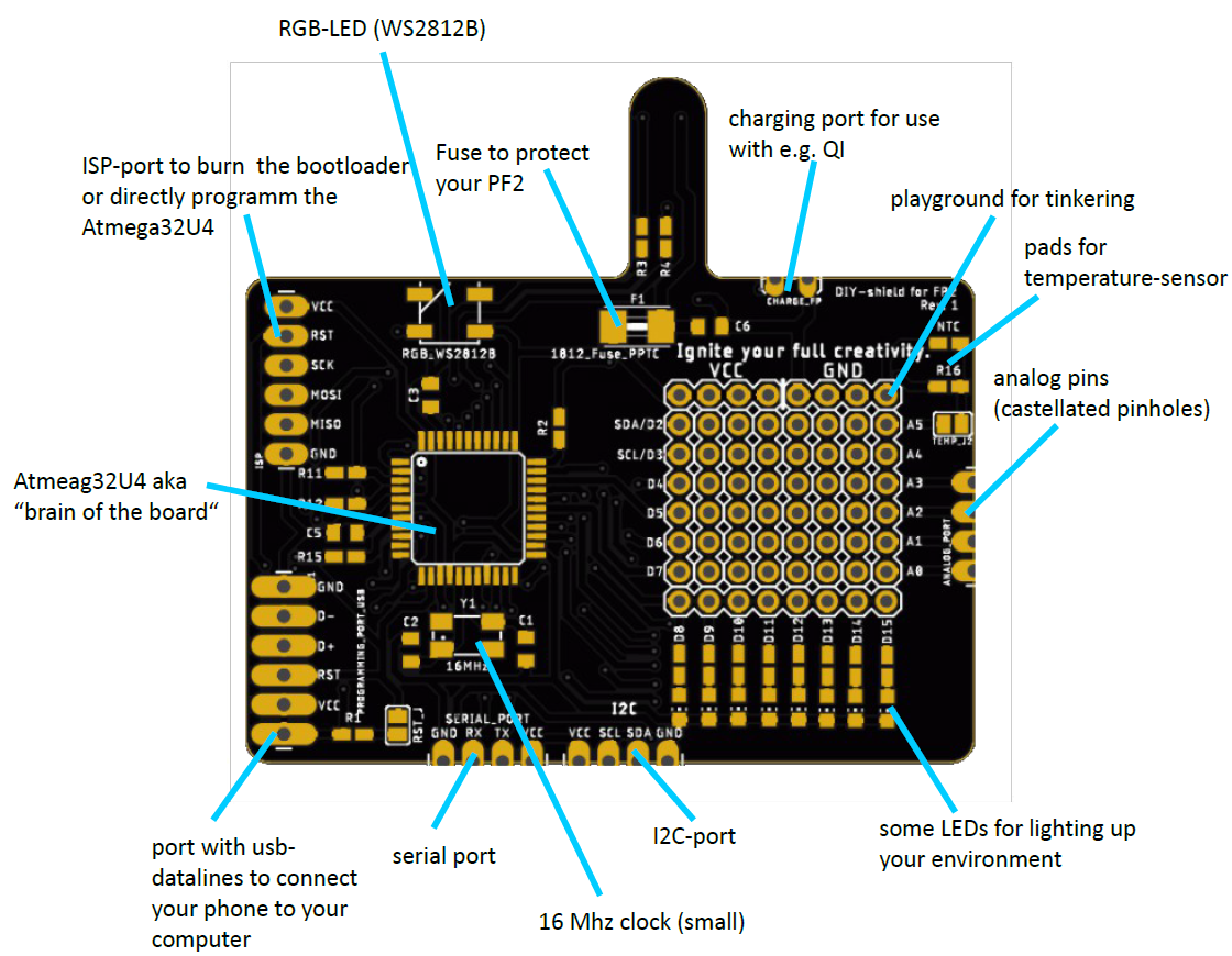
I designed this small circuit around the atmega32u4 and also added some interface-connectors for I2C, ISP and some analog pins for later hacking purpose or for tinkering around with this board as basicboard.
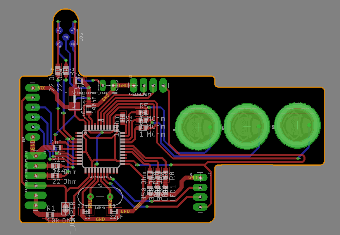
Tada and this is the PCB. It`s not completely finished but I think definitly on a good way!! If you notice some issues or have some ideas about this project please tell me !!
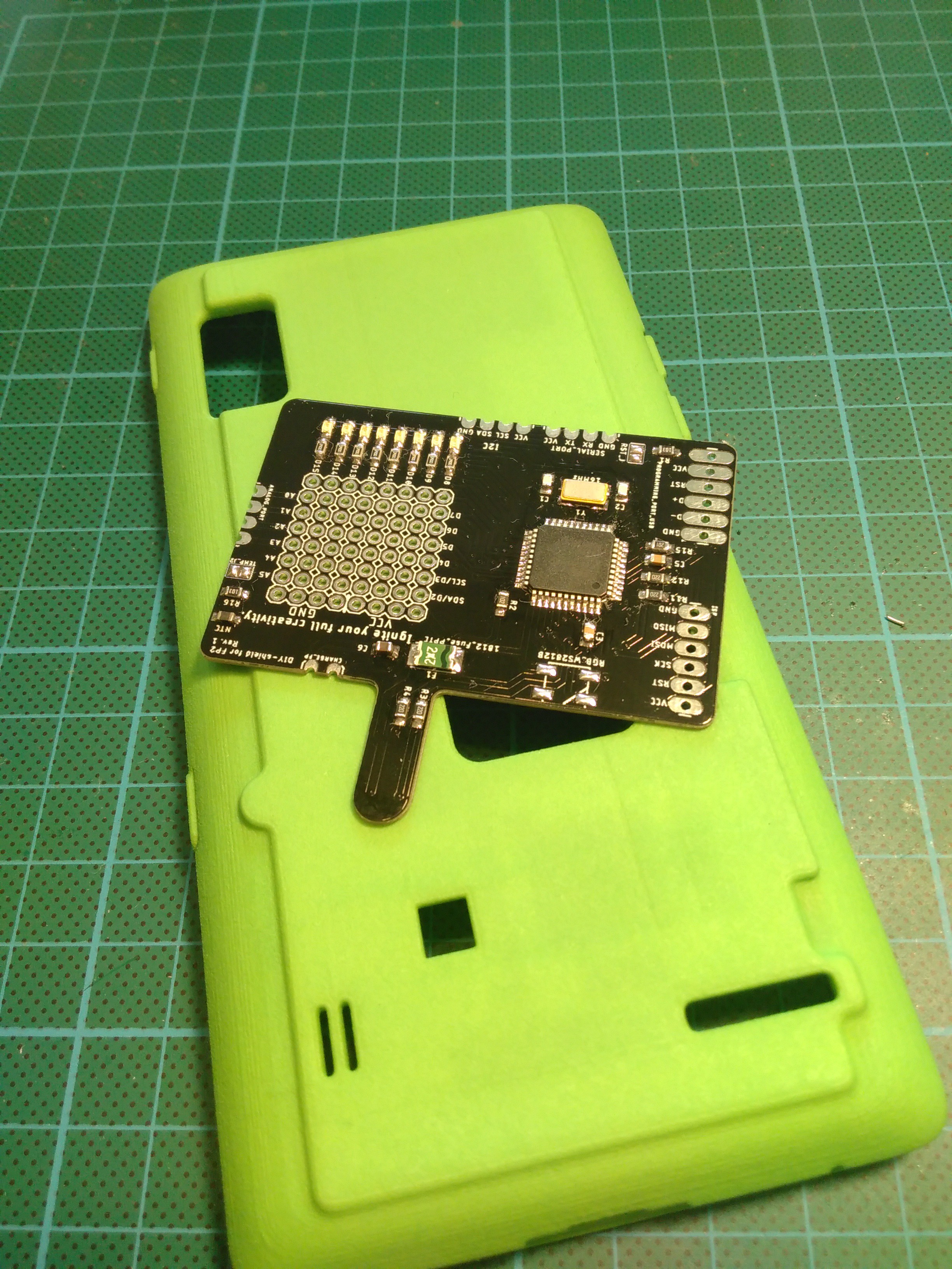
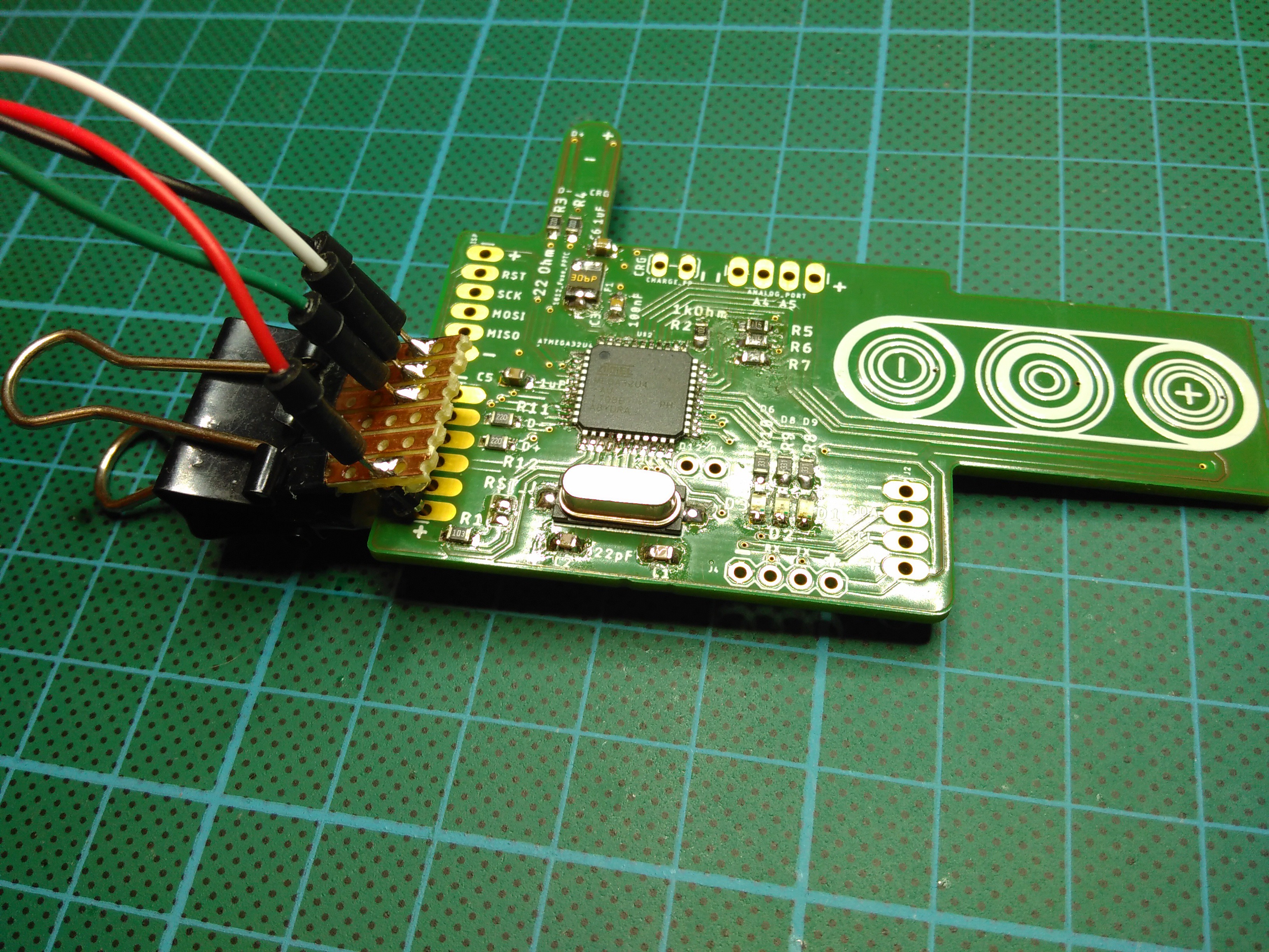
4. Soldering the PCB
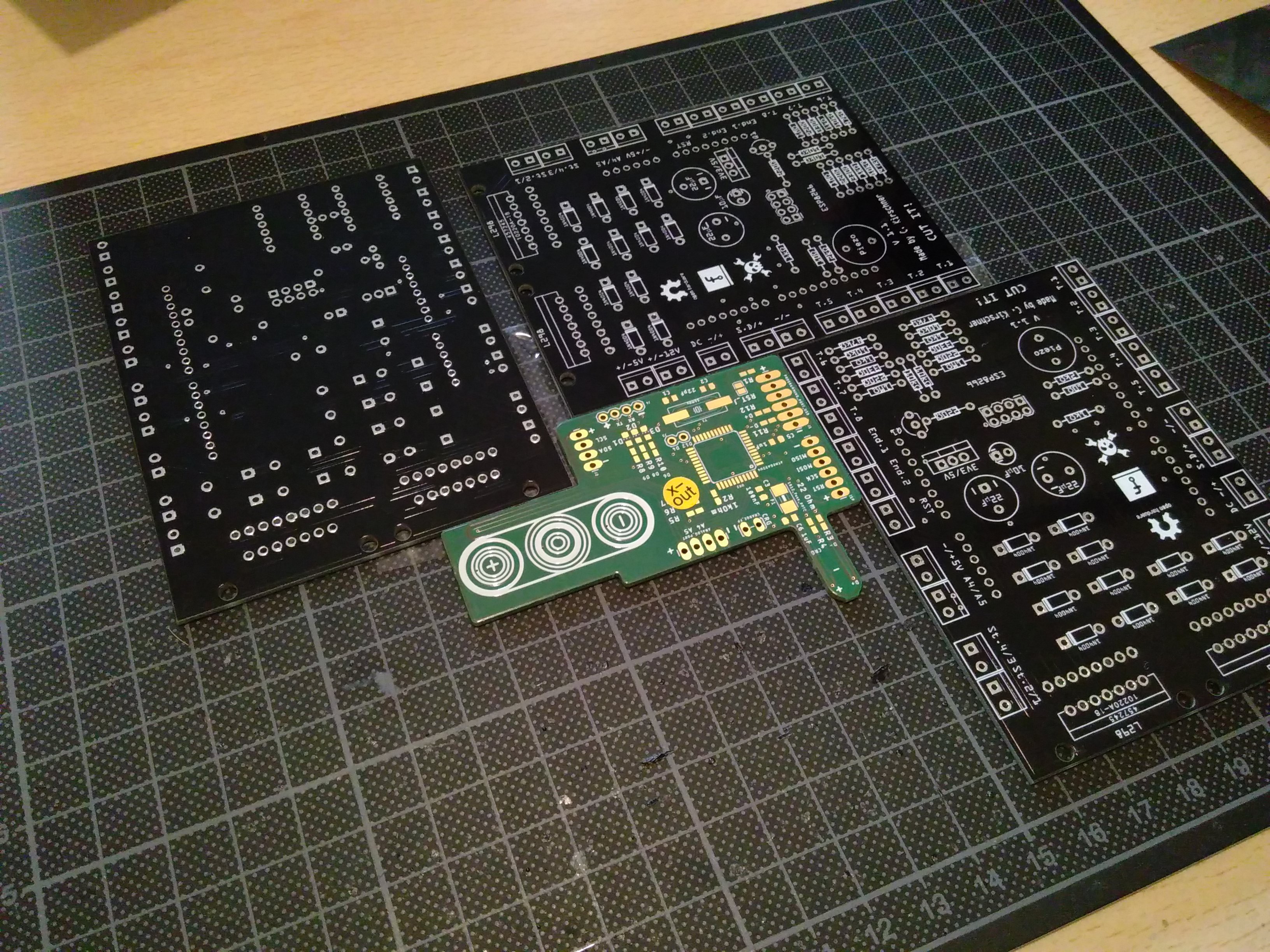
I grapped some unused old pcbs which I had laying around (same height as FP2-pcb) and secured them together in a rectangle.
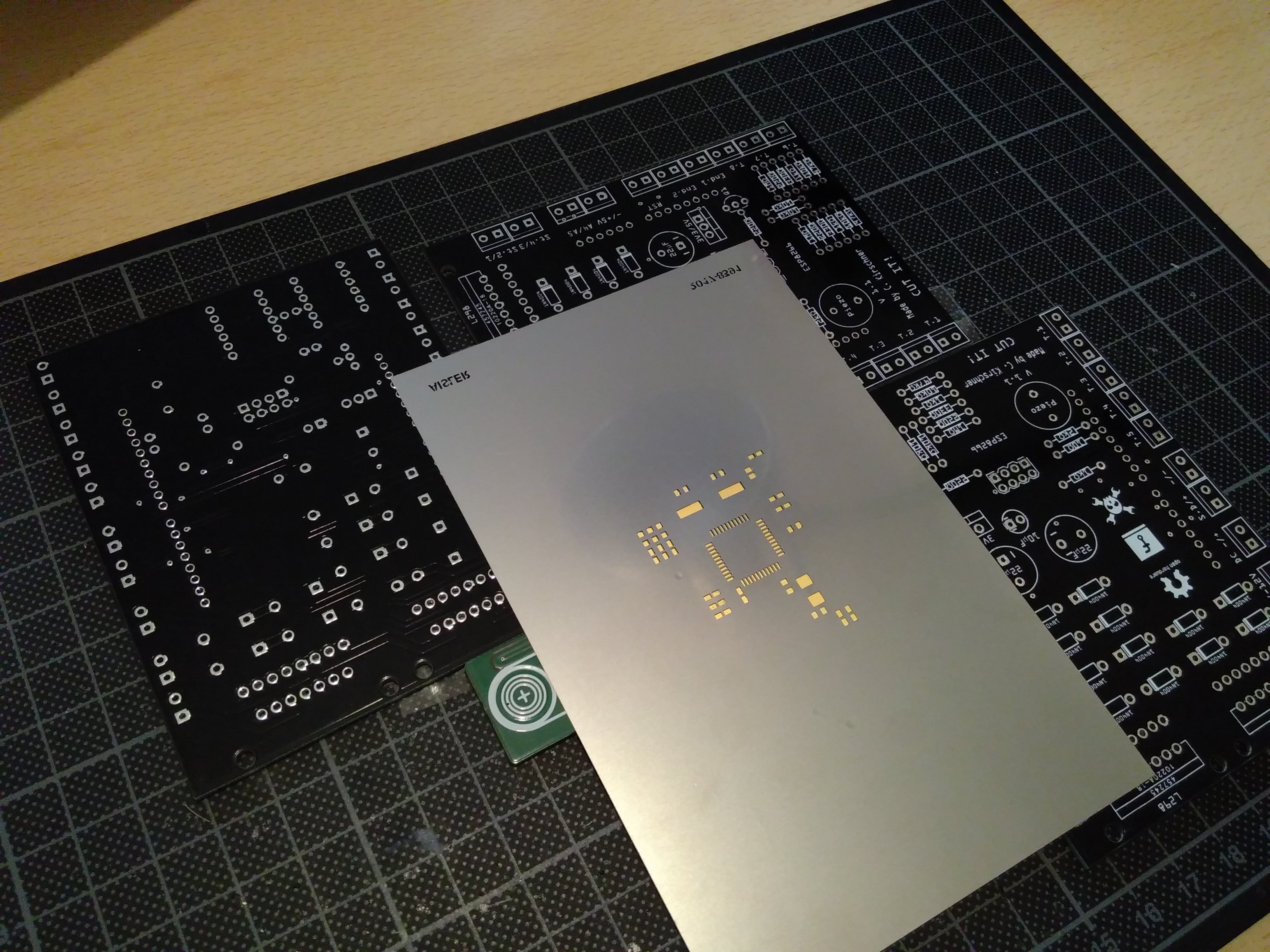 In the next step I attached the stencil to the PCB with some clear tape to keep it in Palace when the solder paste is spread with a scoop. Then I placed all parts according to the board-designe and soldered it with my TS100 and a small tip.
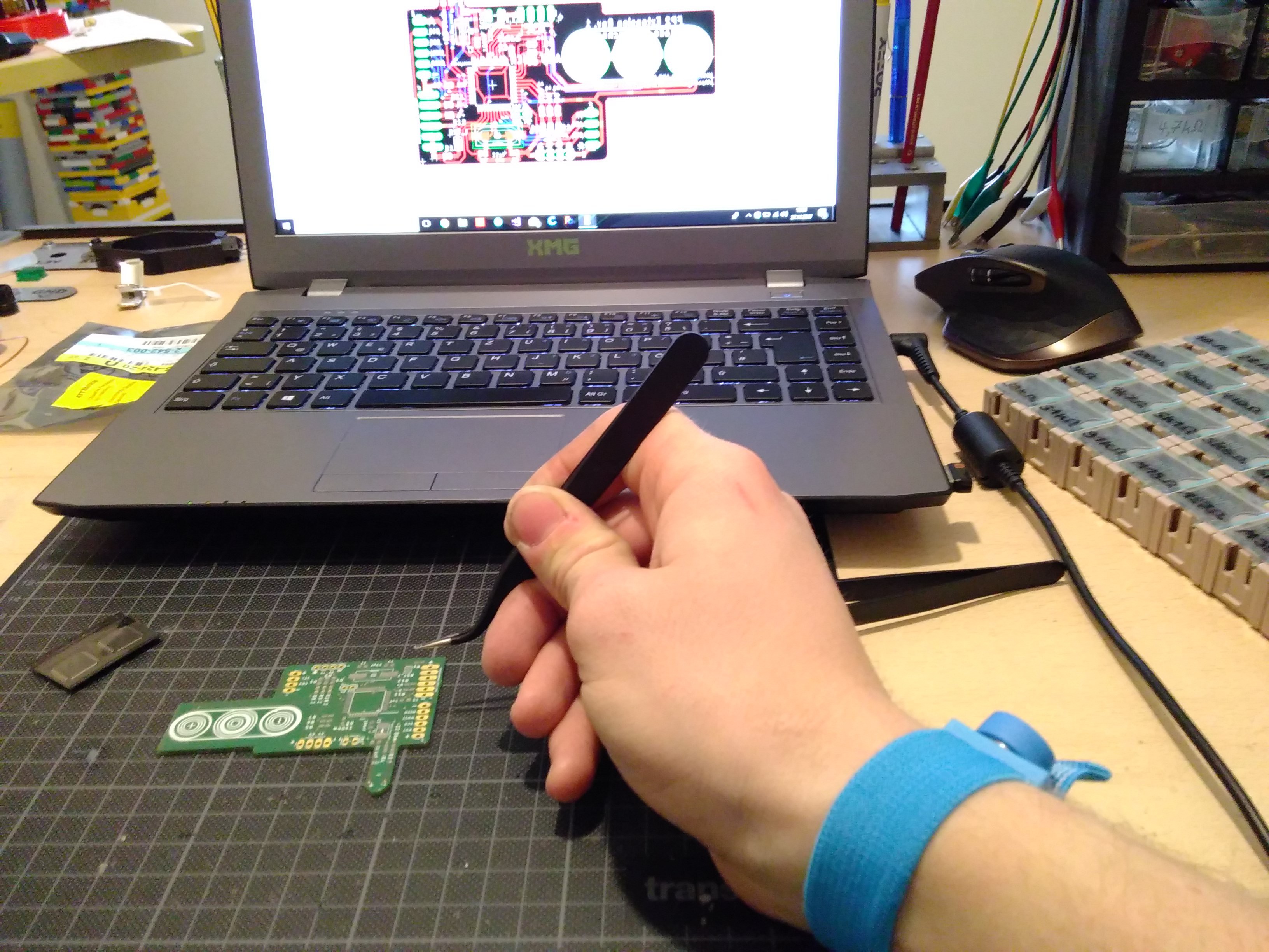
This is the result and I'm pretty happy with it:
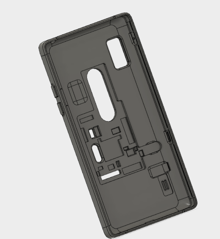
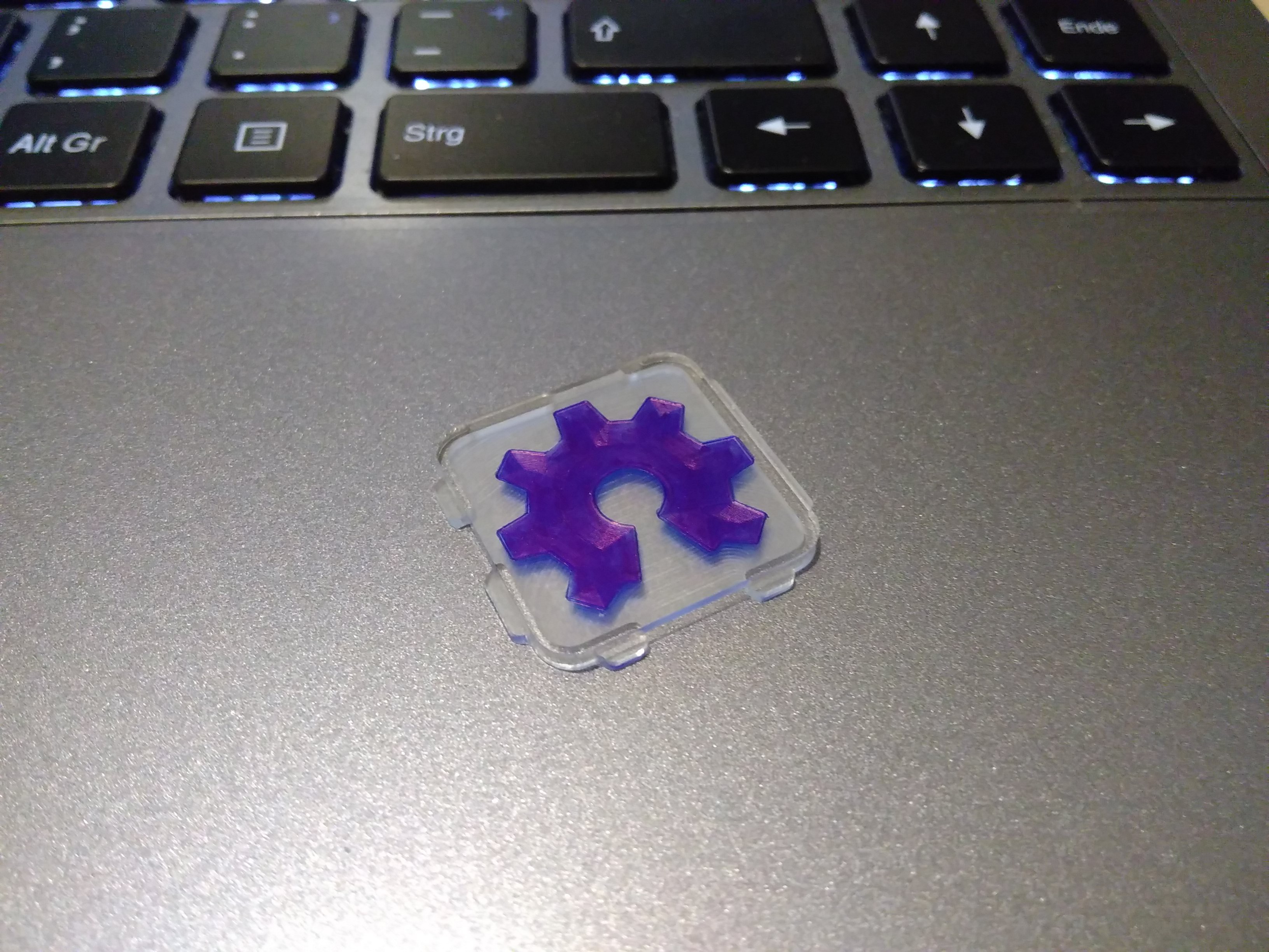
5. Making a fitting case for the pcb
After hours of tinkering and searching for 3D-files of other cases made for the FP2, the company released it`s 3D-files of their cases. This boosted the hole thing immediatly and I was able to do some productive constructions. The result is....
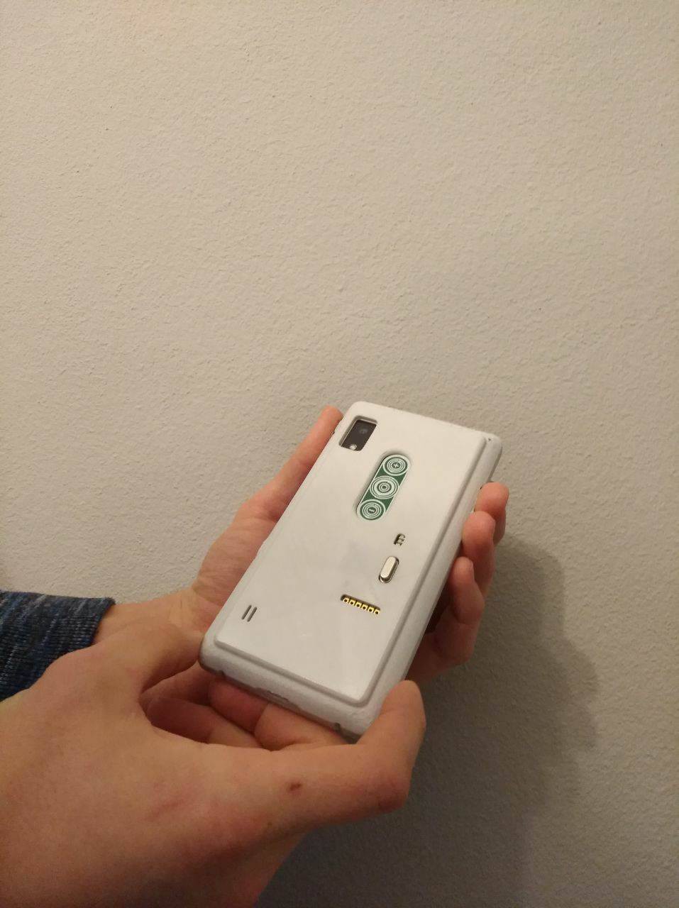
6. The good feeling
I printed the case in flexible filament and it went quite nice :)
Here is the result of my work:
7. Next step
I´m really happy with the good result I achieved. The next big step will be to develop something like a proto-shield, where you can tinker savely and fast.
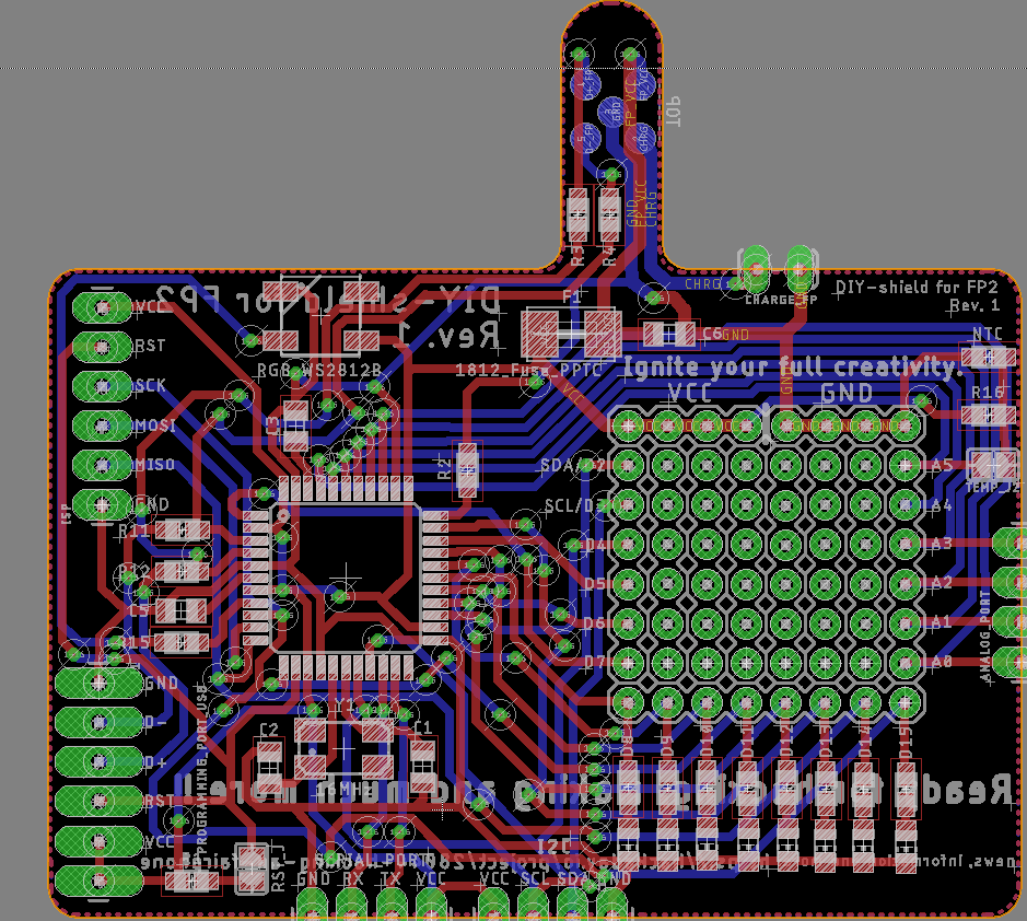
This PCB will have all kinds of interfaceports like I2C and so on. And I also plan to have a pinhole-grid. So you can say, this will be pretty much like the Arduino-setting.
8. Designes have to be made
Here is the result of a few hours of tinkering!! :)
I ordered those boards. Can´t wait to get them :)
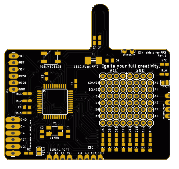
Features of my new PCB:
-> tinkering-area
-> more LEDs
-> interface ports
-> temperature Sensor
-> WS2812B
-> castellated pinholes for interfaces, analog pins and charging port
-> thickness of the PCB around 0.8 mm
-> Atmega32U4 => HID
-> new smaller crystal-package
9. New designed case
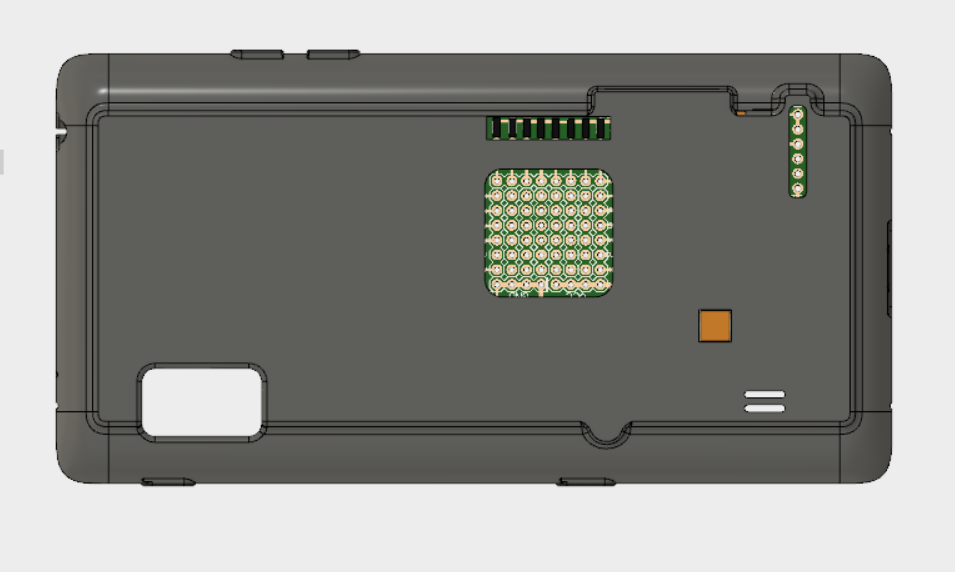
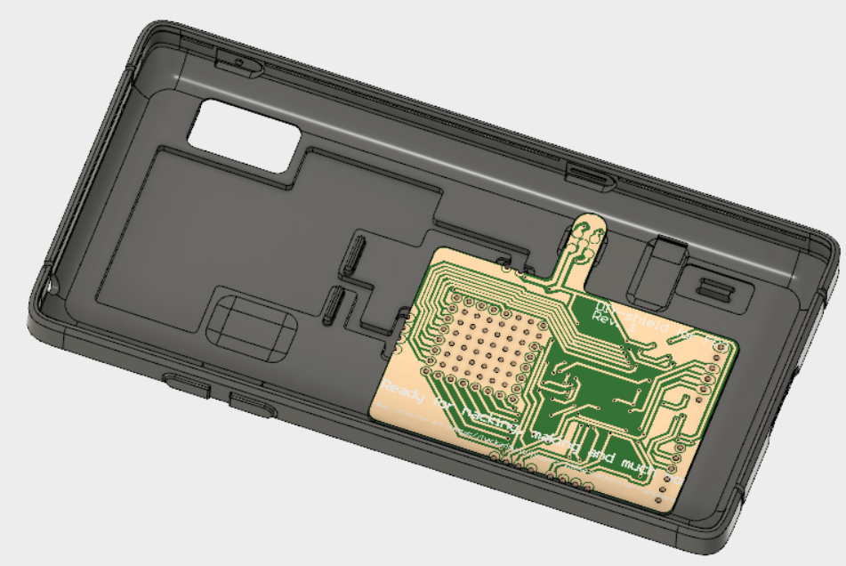
I ordered this one on Shapeways and it also will be offered on my shop.
Let´s hope SLS is the way of success!
10. What did happen?
Yeah, what did happen to this project ? Quite alot!!
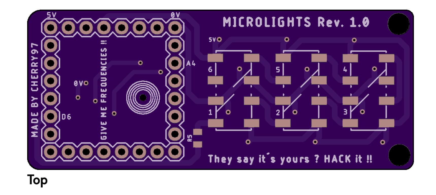
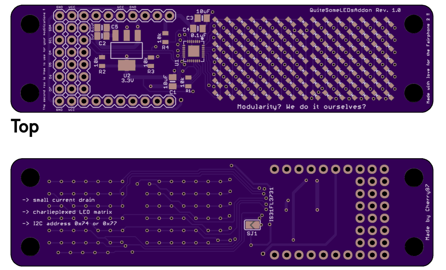
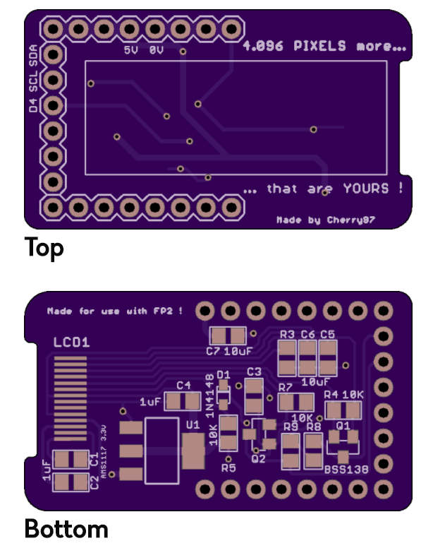
=> The new DIY-shield was a real success and is still fun to play with!!
=> SLS was or still is the best way to print the cases for the PCBs.
=> What did I build with the DIY-shield? A few different things, but I think you like it !!
=> MICROLIGHTS (a soundreactive shield with a few neopixels):
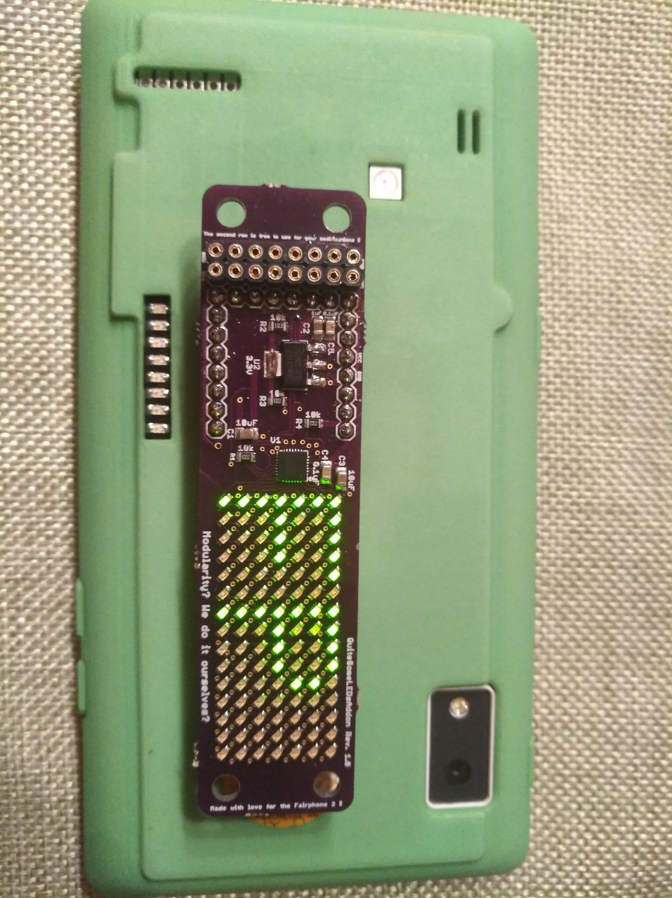
=> QuiteSomeLEDsAddon (105 LEDs to play with)
=> a OLED-addon (this has no special name...)
11. FP2 Extension Control
For easy use and fun for everyone most files are OPENSOURCE and there is also an APP free to download in the PLAYSTORE!!
I hope you like it !!!
And before I forget it, those two github-pages and the people behind those were a big help to gather some informations:
https://github.com/dirkvl/FairPhone
... Read more »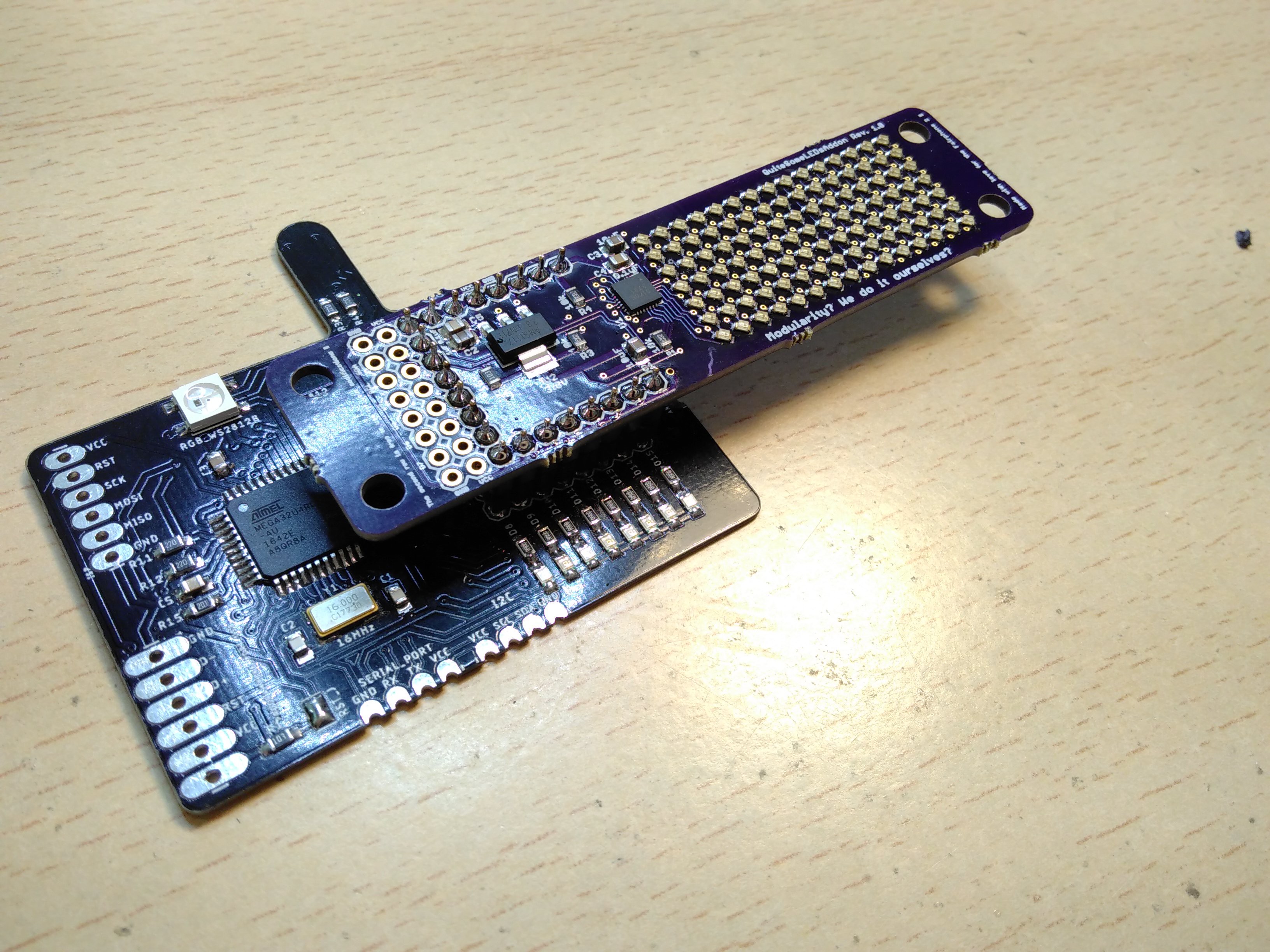
 Lithium ION
 Jithin Sanal
 ElectroBoy