0%
0%
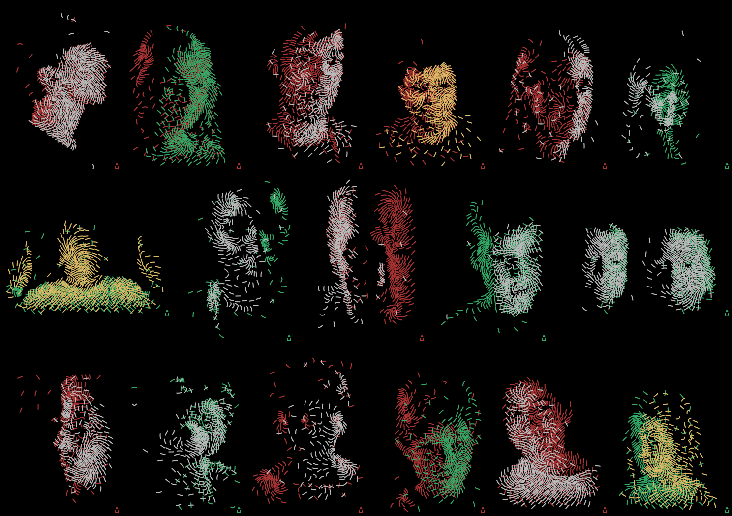
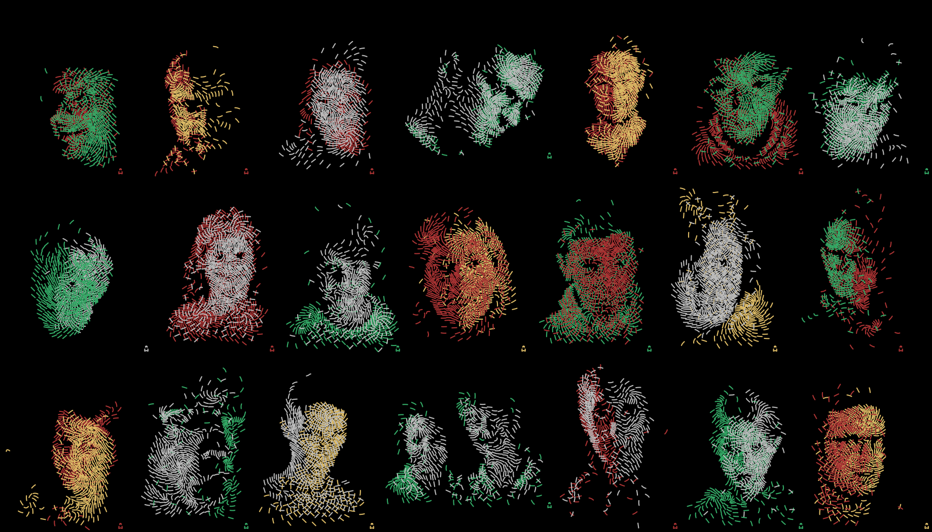
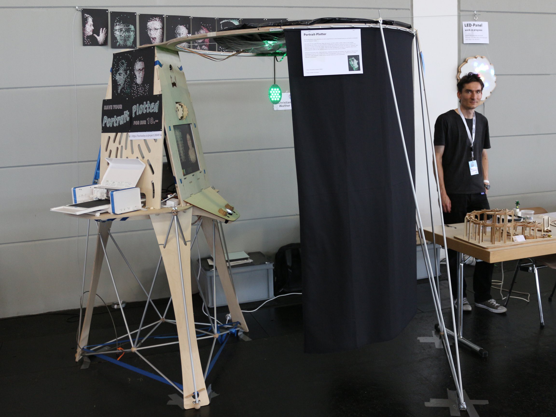
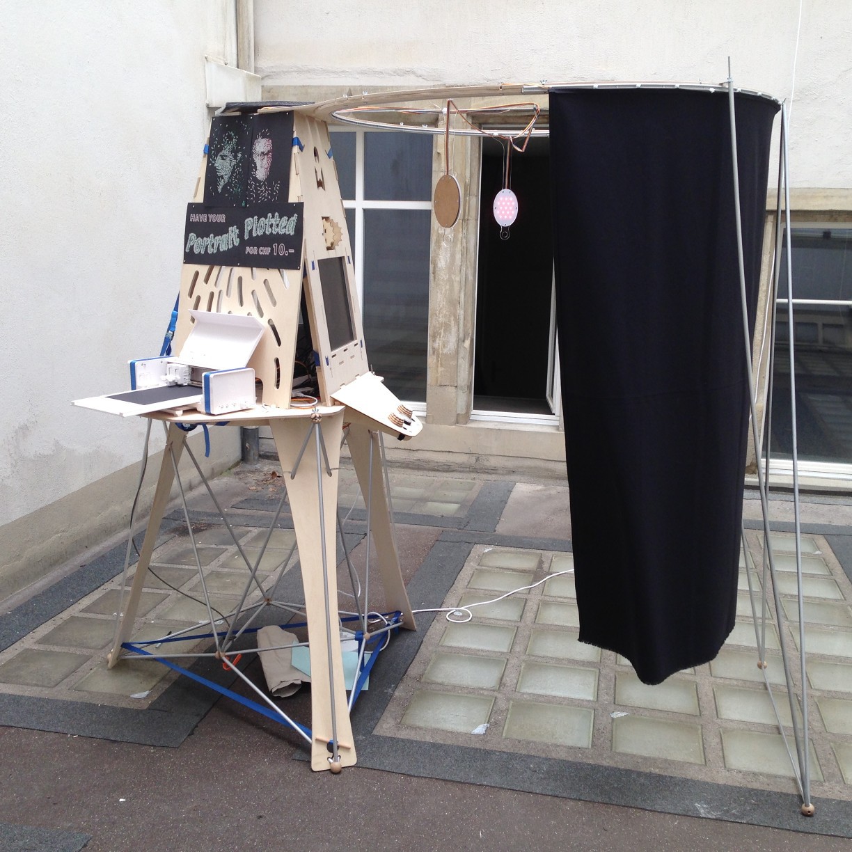
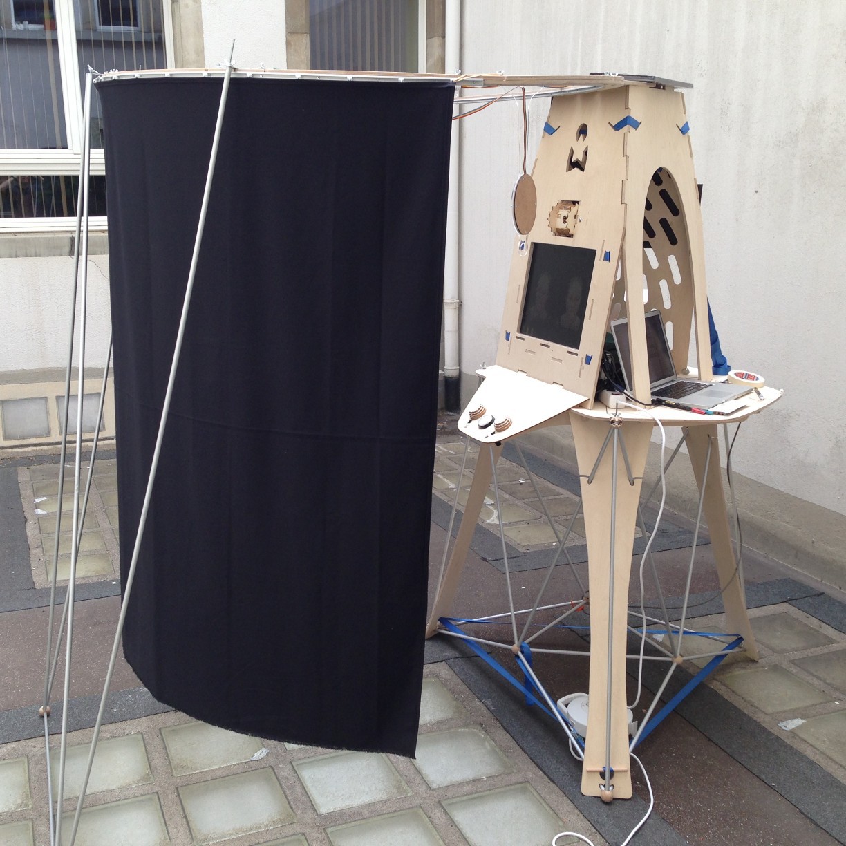
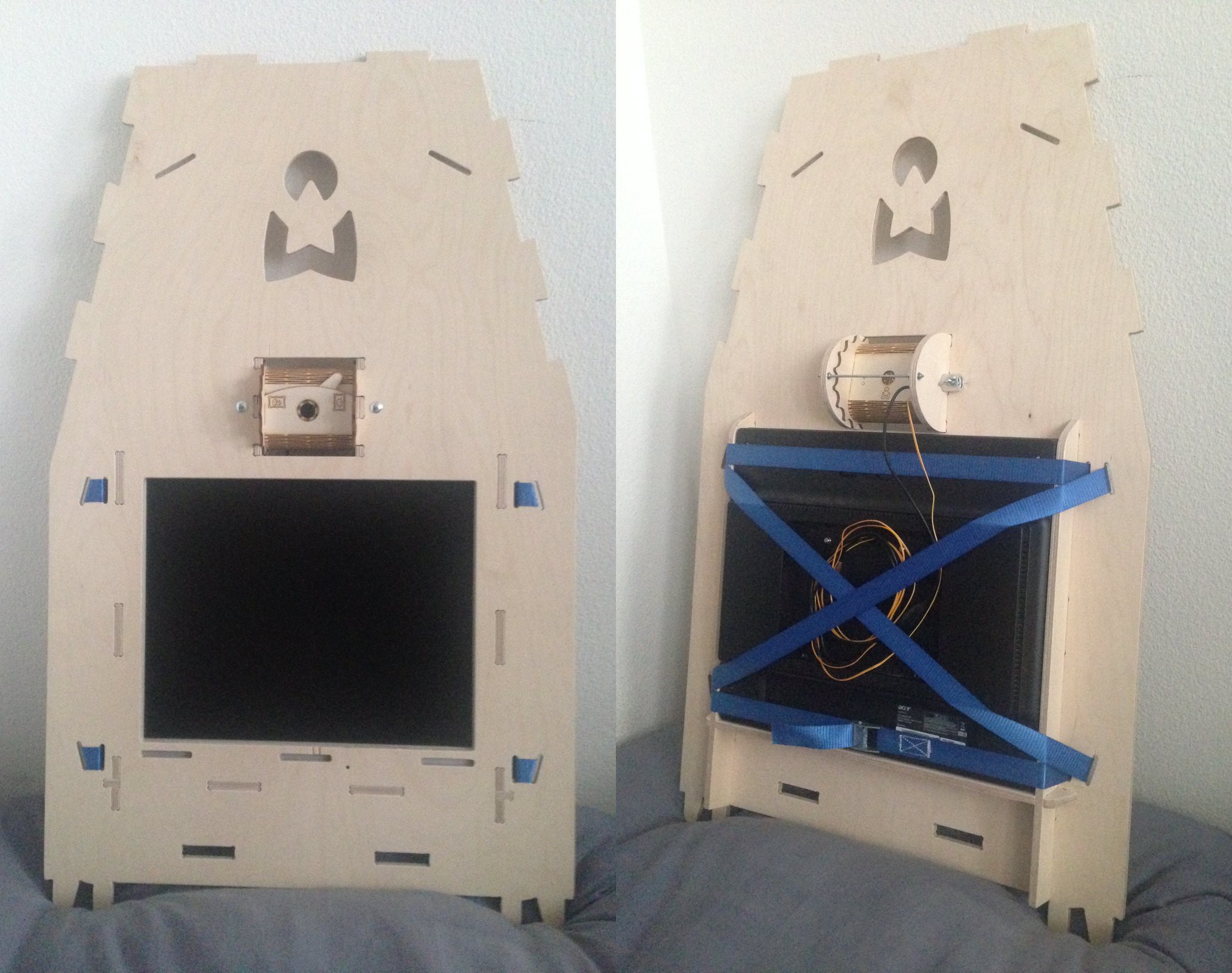
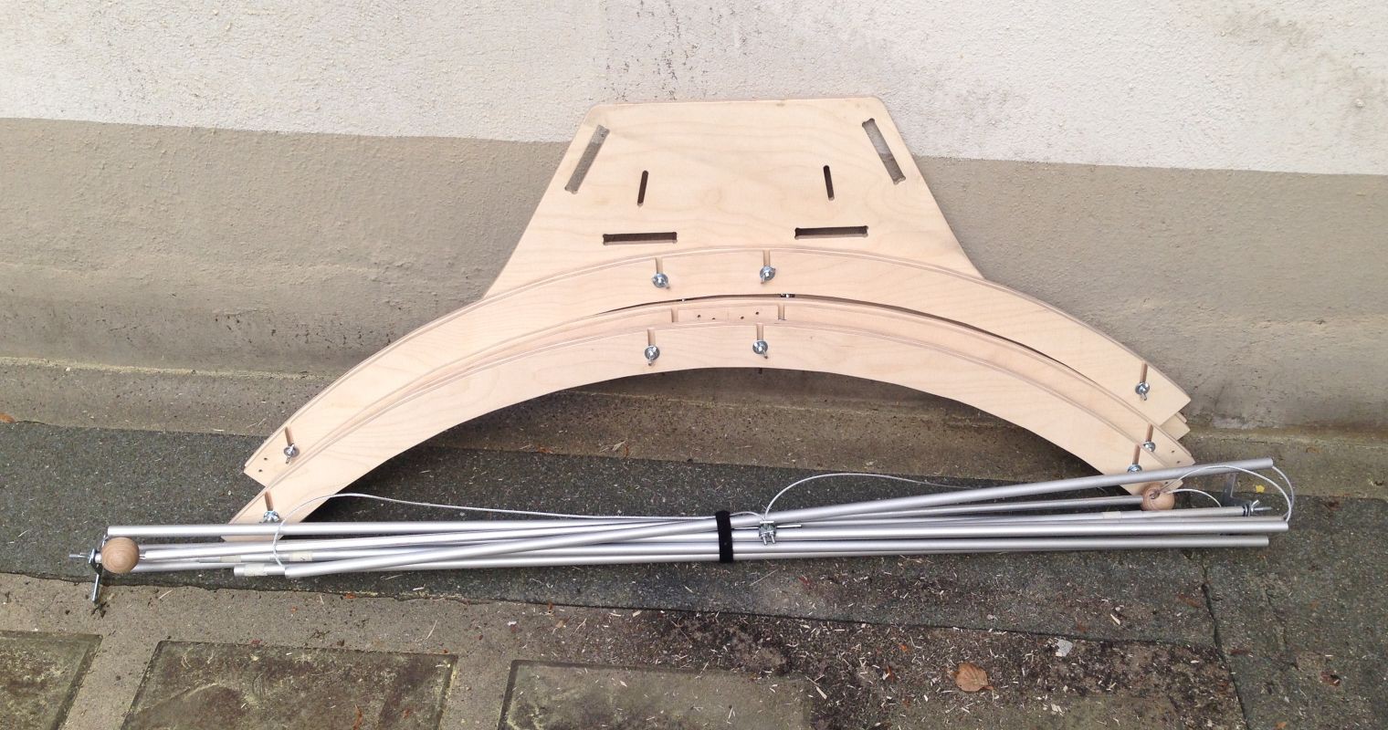
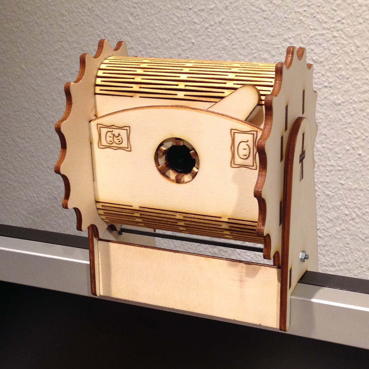
Portrait Plotter
An interactive installation that takes your photo and paints it on paper.
 Christian Walther
Become a Hackaday.io member
Already have an account? Log in.
Just one more thing
To make the experience fit your profile, pick a username and tell us what interests you.
Pick an awesome username
hackaday.io/
Your profile's URL: hackaday.io/username. Max 25 alphanumeric characters.
Pick a few interests
Projects that share your interests
People that share your interests


 Ahron Wayne
 andyhull
 Daren Schwenke
 xD
xD
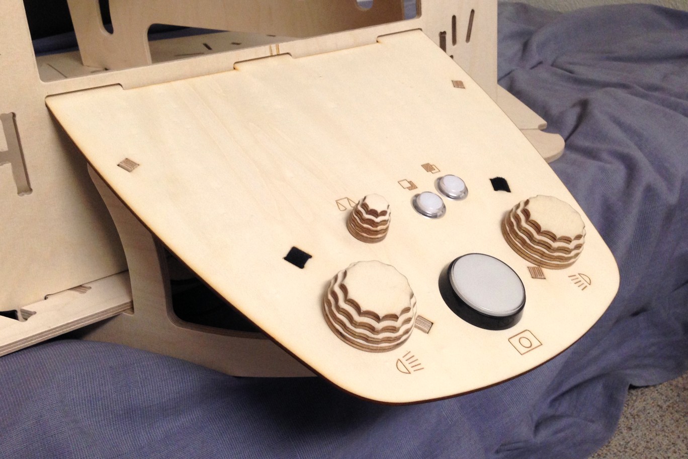
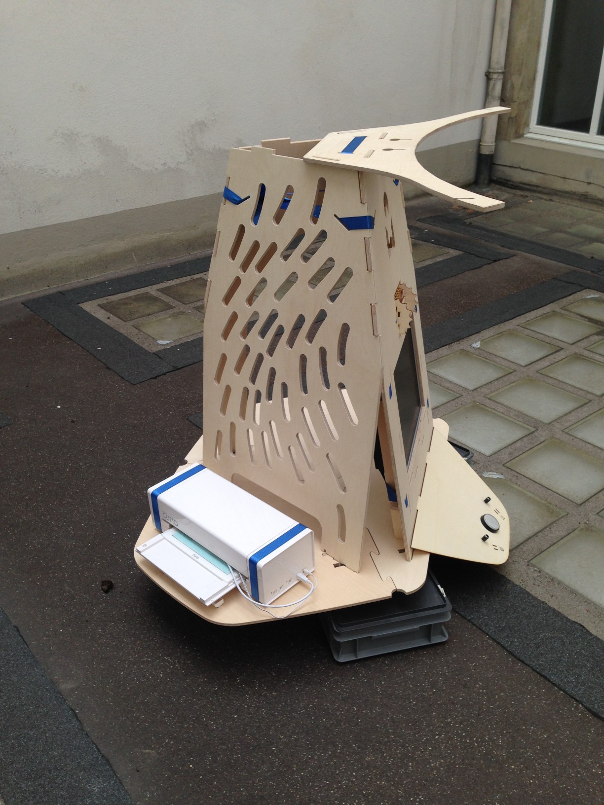
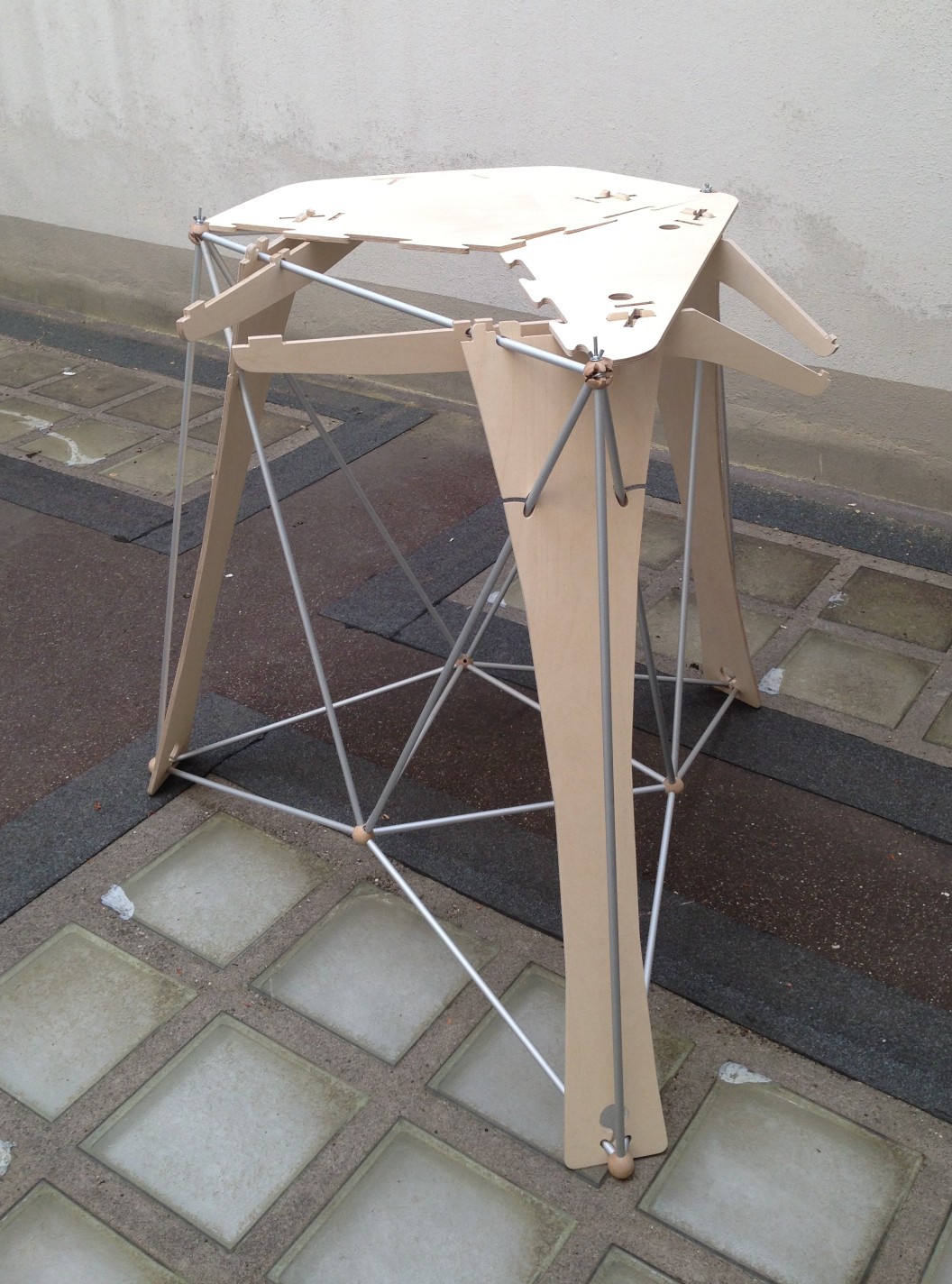
1. Your table design is amazing (and this isn't even a furniture project)!
2. I think you might get better results on certain images (specifically those where there are regions of different average luminance that you still want to include in the output, like the two-faces example in your first log entry) by applying a high-pass filter before the gamma step, but after background removal (or identify the background before HPF and then apply that mask later). That'll bring those regions to the same overall luminance, while preserving detail.
3. Do you have a video of your plotter working? I love pen plotter videos.