 Paul Andrews
I finally had time to get around to building one of my clocks. I spent an hour or so labelling all the component bags so I wouldn't be searching for components once I had the solder paste applied. Then I taped the board to my bench and used the stencil I had made at OSHStencils.com to apply solder paste. Once done I started adding the components to the board and finally wandered over to my reflow soldering station:
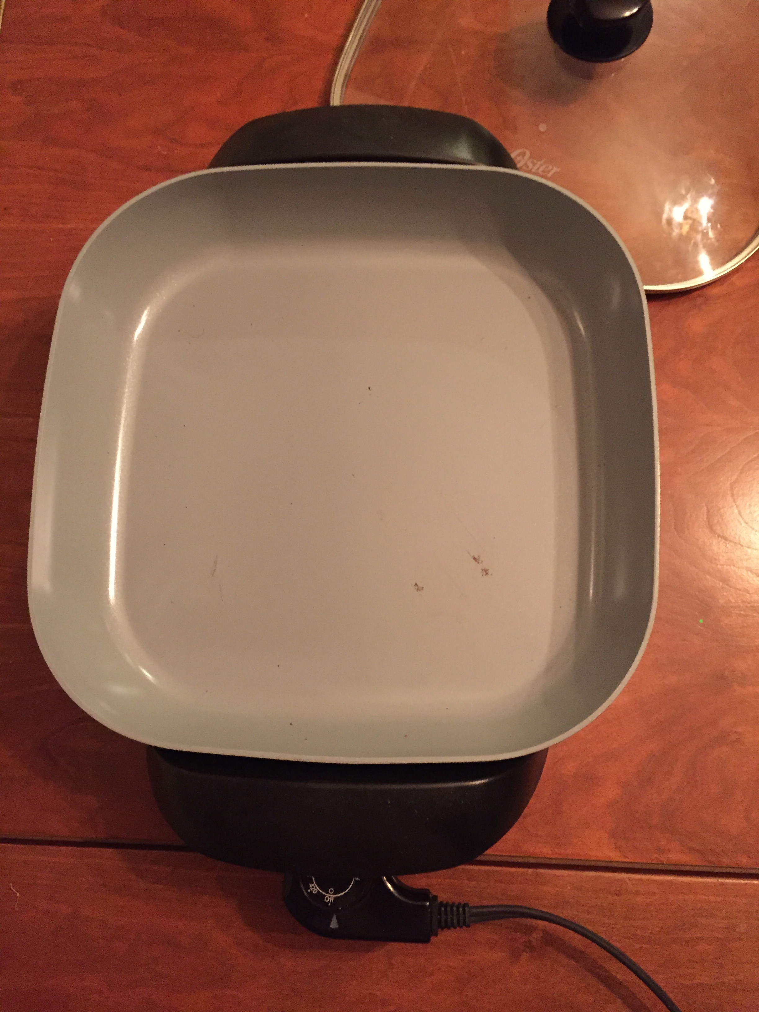
Yes. Its an electric griddle. About $40 from Target. As this board was bigger than all the others I had made, I needed a special tool to load it into the griddle:
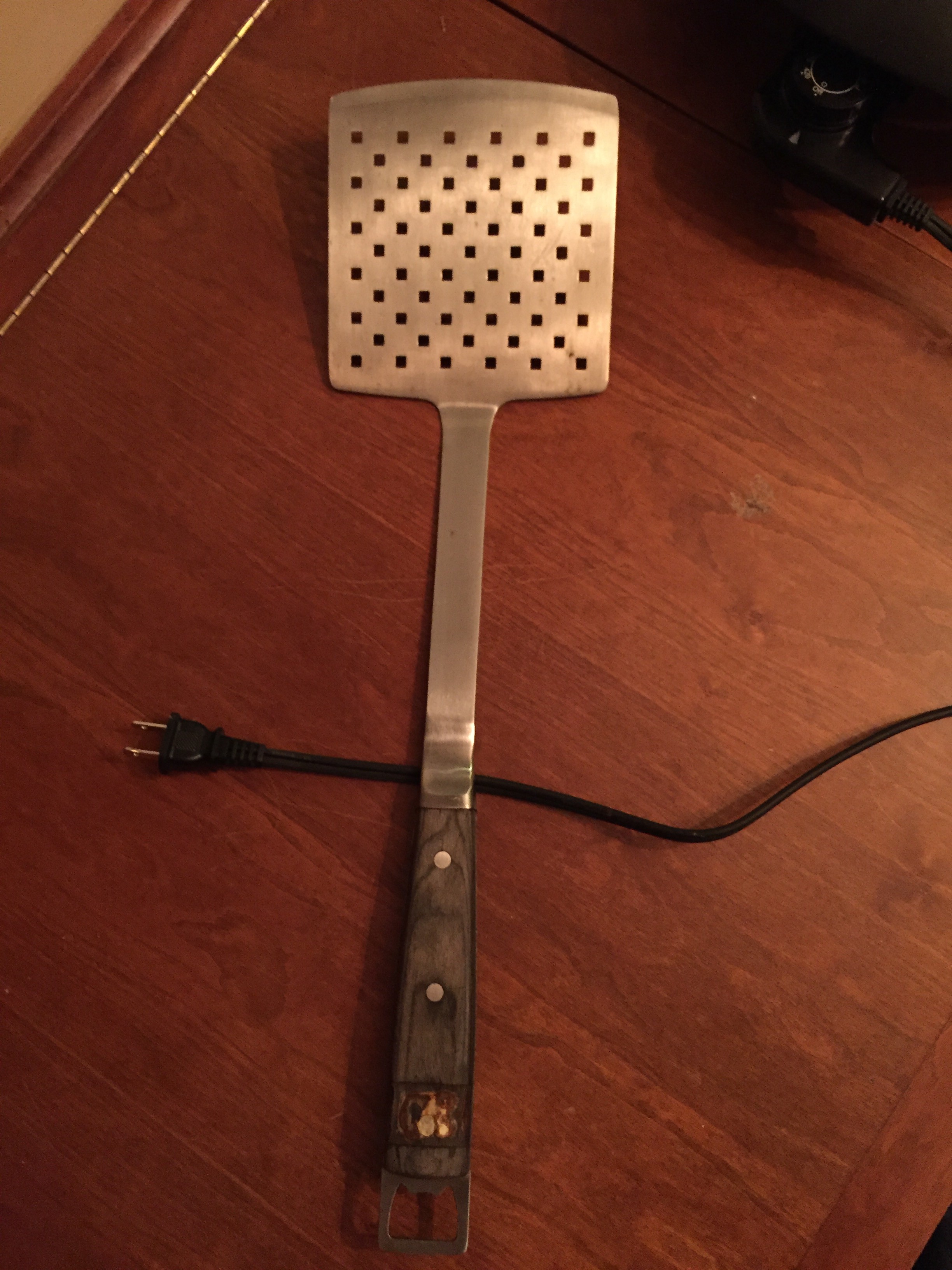
I knew that over-sized spatula would come in handy one day.
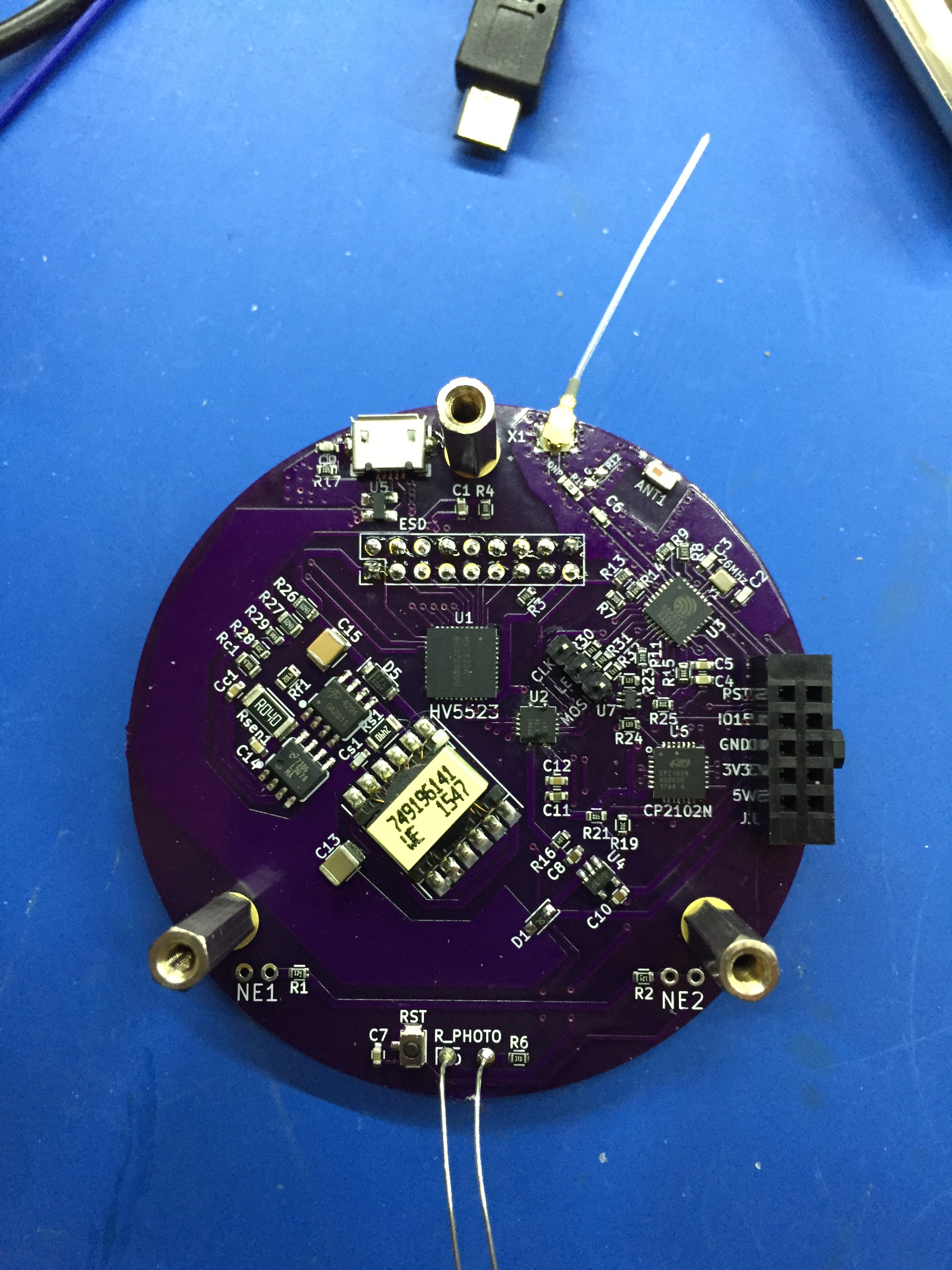
Anyway, this is what I ended up with:
Testing went surprisingly smoothly (at first):
- My PC recognized the board when I plugged it in
- I could configure the CP2102N USB-UART chip using Silicon Labs config tool
- I uploaded the clock program and assets to the ESP8285 (U3 in the picture above)
- My phone saw the access point presented by the ESP8285
- I could run the web GUI
Then I plugged a tube in and things weren't as I expected: All of the digits were lit up and the LED backlight wasn't! There followed about 2 hours of debugging. First, I hooked up the Clk and MOSI pins to my oscilloscope - they showed that the ESP8285 was producing the right signals for the HV5523. However, the signals are level-shifted through a TXS0104 - I very carefully managed to stick the probe on the output side, and there was nothing. So that was it. I spent an hour or so trying to touch up the contacts with my soldering iron and eventually I succeeded! One or other of the +5V or 3V3 connections had been bad (note to self: Don't put vias on really small pads!). Now I could see the clock displaying digits, except that it was displaying all but one of the digits - in other words it was inverting the outputs. I took a look at the schematic and for some reason I had tied the HV5523 polarity pin to ground rather than +5V. Fortunately, this was easy to fix in software, and finally I had a functioning clock:
If you're wondering, the dangling thing on the wires sticking out the front is a LDR - at some point I will be putting this in a case, so I didn't want to trim the wires until then.
There is one other problem with the hardware: I should have cut a notch in the PCB where USB connector is, without it it is pushed up at an angle by a lip on the connector, however it still works.
I like these things so much that I can't wait to assemble my other two boards and scatter them around the house. Unlike a full 6-digit clock, they easily fit anywhere.
When I get a bit more time, I will add upload all the CAD files and source code to GitHub and add links to everything.
Discussions
Become a Hackaday.io Member
Create an account to leave a comment. Already have an account? Log In.