 Eric Hertz
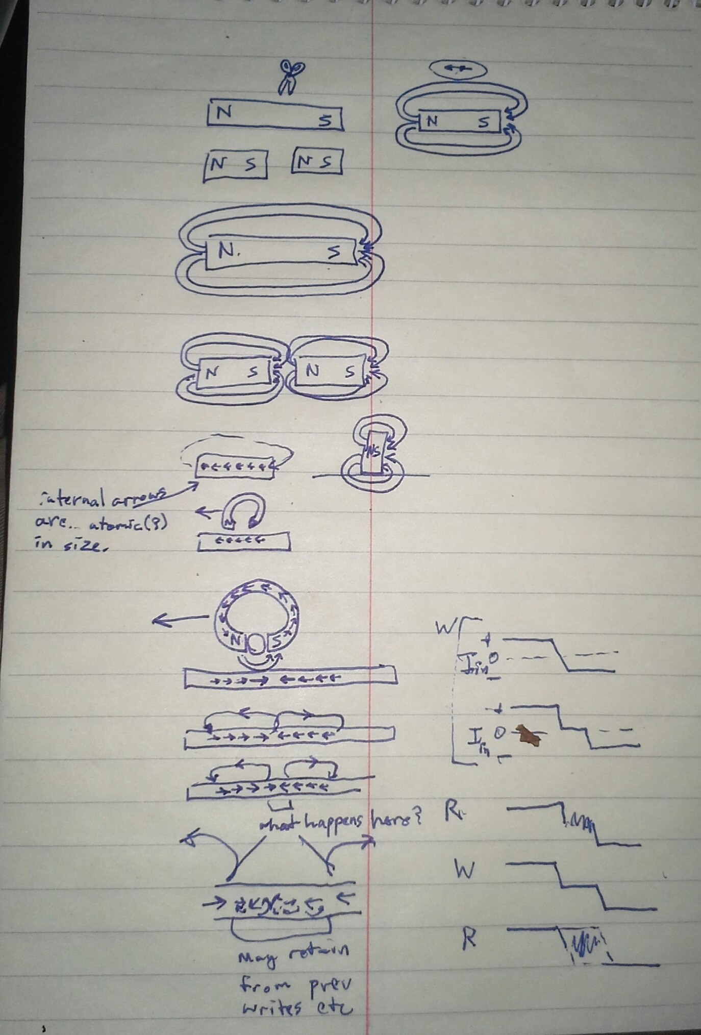
ok, unanswered Q's from the last log... had to remember physics lessons from nearly 20(?!) years ago....
If you cut a magnet, you get two magnets.
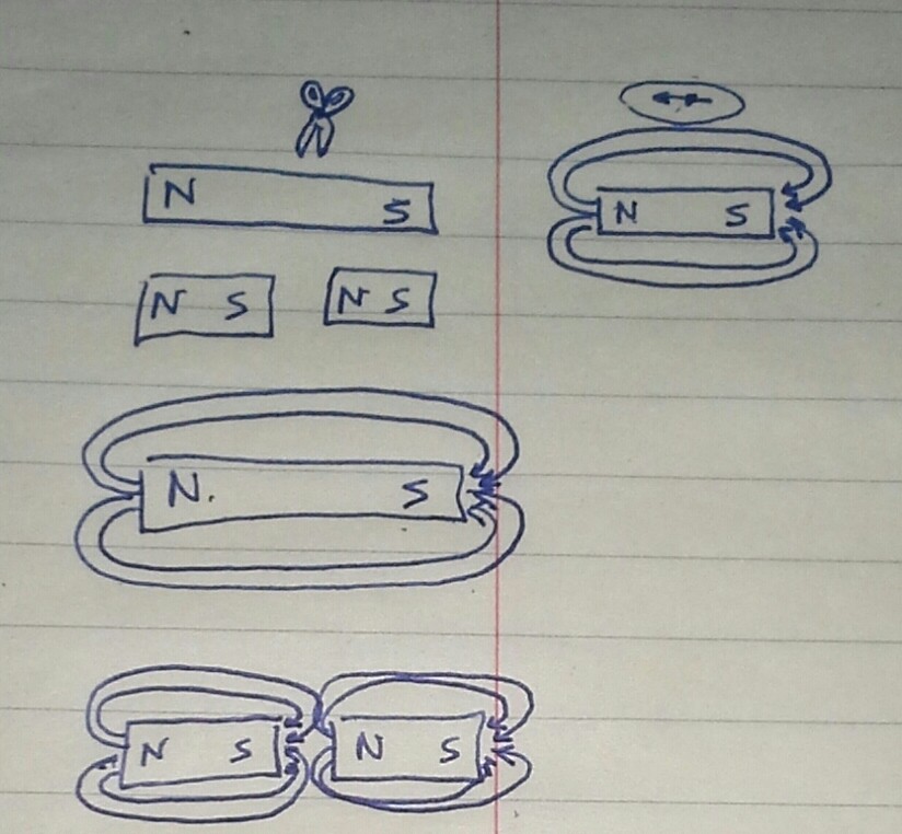
The magnetizations are at an atomic or molecular level... each atom or whatever is a magnet, with both poles. This is demonstrable by, e.g. cutting a bar magnet into successively shorter pieces, all the way down to an atom-width, it'll still have a north and south pole (assuming the cutting process doesn't interfere!).
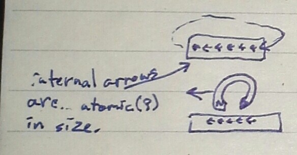
So, really, the only field lines are those extending from the ends of the magnet. Those between the molecules are so close as to essentially not extend outside the magnet. Thus, those have no effect on the R/W head.
Thus a long string of consecutive "bits" of the same polarity look like a long magnet with constant field-lines extending from the *ends* and wrapping around outside the media, in air, before reaching the read-head... right?
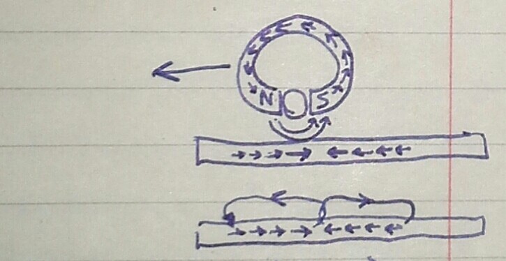
Flux, as I recall, is essentially the amount of field-lines (and direction) through some given area (e.g. the gap in the R/W head).
Floppy drives detect *changes* in flux, rather than an amount or direction.
It's impossible that a write-procedure could switch the direction of the electric current, and thus the polarization, instantaneously. "What happens here?"
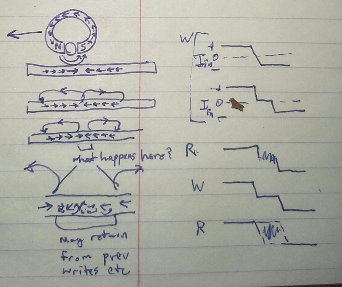
The disk keeps spinning, meanwhile the write-head is essentially Off, at some point, and likely for some time, before ramping to the other polarity. Imagine "crossover distortion" from linear amplifiers. Also contributing: when the write-head has too little current to actually change the magnetization--during the ramp--for some time on either side of the crossover.
So, during the crossover/off time, the magnetic particles (that's the word!) on the portion of the disk spinning under the write head will not be written with any polarization. It will retain what was already there. (there is no "erase before write" procedure on floppies, unlike audio cassettes).
AND Strike Two for PWM-Nibbles.
Because...
During the crossover-time when written, the original polarization already on the media could be anything, could be noise, or could be same- or opposite-polarized from a previous write.
If same-polarized, the read procedure will detect a flux change not where it was written, but some time *after*. And now our measured PWM duty-cycle has increased.
If opposite-polarized, the read should detect the flux change when it was written (right?).
And, then there may even be plenty of room for numerous flux-changes to be stored and detectable within that space... There, I imagine, the read-back circuitry probably filters out repeated changes, reporting only a single low /RD pulse... ("0.1 - 1.0us" hmmm)... at the first flux-change detected. Much like a debouncing circuit for a push-button.
OK, so... I dunno how fast crossover is, but 1/16th of 1us may be asking a lot. So, it's likely my PWM-nibbles are being mangled here (as well).
Plausible Mitigation-tactics?
Write the same polarization *everywhere* on a track (erase) before writing data. Might be possible. But, now, the opposite-polarity case will read-back a different (though, maybe predictably) value than the same-polarity case. Maybe doable... May require some header-data to *determine* the polarity-sameness... as, there's really no way to choose nor read back polarity (again, only *changes* in flux are written/read with the /WR and /RD pins).
Maybe a track-erase could be *immediately* followed by a track-write? Though, as I recall, detection of the *index*, once per circle, causes the write procedure to abort... The erase-then-write procedure will probably require a pause inbetween, disabling then re-enabling the write process (via the drive's /WriteGate pin). So maybe no-luck guaranteeing the first written flux-change--after a full track-erase, indicating the start of the first PWM-nibble--will actually have the opposite polarization to that which was written during the erase procedure. In other words, it's probably aboht 50% likely the first flux-change written after an erase may get missed entirely, (thus, again, sectors in normal disk-usage have headers of repeating data that can be recognized by the controller, for synchronization).
Handily, Since each PWM-Nibble consists of Two flux-changes, the data-value offset (due to erase vs. write polarity-sameness) should be constant throughout each a single track (or write-process, should I eventually consider sectors). But unlikely to guarantee it to be the same on the next track.
Possible.
Also, this definitely brings to question whether the system could work with different drives. Could this synchronization process automatically determine each drive's "off time" and propagation-delay characteristics? (assuming jitter isn't an isssue) I think that may actually be inherent to the necessary offset-detection design, woot!
....
Another concern is related to the erase process. First-off, a /WD pulse is technically required within 0.8us after enabling /WG, and 0.8us before disabling. So erasing requires at least two flux changes. I haven't seen any requirement for minimal distances between those two. But a non-varying polarization throughout the majority of an entire circular track (after erase) may enter weird territory. Say a track was half-erased, maybe the field-lines then jump across the disk's diameter, rather than along the track! It may well just be not-allowed to write the same polarization for such long durations! And *that* too may bring into question the feasibility of long-duration PWM...
Also along those lines, an inductive read-head only detects flux-changes, but when the flux *doesn't* change for some time, will the sensitivity reduce?
The inductor's output will eventually return to zero current, rather than positive or negative. Then a polarization-reversal will result in a different current-change than where polarization-changes occur back-to-back. Maybe it'll get missed entirely, due to rail-clamping...
Or plausibly weirder, and maybe more likely, after the inductor-current returns to zero it'll be even *more* sensitive... e.g. fed into a comparator, a tiny fluctuation in current, say from external electrical interference, may cause a flux-change-detection, even though the actual magnetic flux under the read-head has been constant (and plausibly large) for some time!
And, in fact, I think I saw this in my experiments. I attempted to increase the "buffer" duration of the PWM-nibbles beyond my originally-specified 2us, in order to give more time for processing overhead. At 4us and above the recorded-data was completely lost in static, whereas at 3us, the recorded-data seemed *almost* recognizable. And recording a full track with a constant repeating PWM-nibble value resulted in near-silent playback from the speaker, as should be expected.
While that may be indicative of my 'head-zeroing' theory, it also seems a bit strange only 1us could have such an effect. MFM bits are 1us in duration. A string of up to <s>three</s> FOUR '0's is possible, as I recall, (binary '100' = MFM '10 00 01'. That'd be FOUR microseconds with nary a flux-change. Hmmm. And, of course, the '1us' specification is *ideal*, what when a disk is written on a drive spinning slightly faster than 300RPM, then read-back on one spinning slightly slower? 5us seems more reasonable, and probably no reason for tolerances even that tight. And, further-still, this assumes a drive that only works with 1.44MB floppies... what when a 720K disk is used? (Though, as I recall, they do spin faster, certainly not double-speed: 360RPM vs 300). The MFM-bit-rate decreases, (As I recall, 500kbps, though I dun think that math adds up) meaning those same read/write heads and associated circuitry need to cope with up to 8us non-changing flux... Anyhow, I should be able to expect more than 4us.
....
Also, a while back it was suggested to try these early experiments with bigger PWM-Nibbles... why start this project already pushing the limits? Indeed, that was silly of me. And Thanks, @Starhawk for reminding me that I could/should step back a bit.
The next step along that path was to use the next-slower clock-divisor for the AVR's PWM-generators. Whereas before I was using FCPU/1 (16MHz), the next step would be FCPU/8 (2MHz). That, I see now, might still be too fast for this early experiment, when bits stored normally are only guaranteed to 1us resolution. (And, stupidly, I wrote most my code with microseconds as my unit of measure in constants all over the place, a non-trivial rewrite).
So...this project's goals may need some scaling-back :/
Lessee, say I use 16us instead of 1us... maybe I can keep the buffer-lengths the same (2us on either side)... that's like 1/16th the capacity. Which... was originally-planned to be *just right* for my LCD display at 8 colors... 1/16th of a screen ain't much... Maybe B/W, half-screen... weee!!! Heh, then I could just use MFM. We'll see.
Discussions
Become a Hackaday.io Member
Create an account to leave a comment. Already have an account? Log In.