 Gerard te Meerman
The standard operation of this device is to give the standard pulse to the speedometer as long as there is no deceleration measured. If there is a deceleration, a series of pulses will be generated that shows for 100 revolutions of the wheel the energy loss in watt/10 as speed in km/hour.
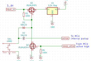
The output is using the tri state property, by letting the output
float until an output pulse is needed. This pulse is then generated by making the output active for a short while, following an idea that I picked up from Horowitz and Hill the art of electronics (third edition) The outputs of an attiny85 are N mos enhancement FET drains, which act as a resistance towards ground. This is interpreted by the display unit of the speedometer as a closed contact.
After a measurement the power signal is given for 100 revolutions and the unit
switches to normal operation until the next deceleration.
The power calculation assumes an equivalent weight of 100 KG for bicycle and rider, which includes the effect of the momentum of the wheels. This value is set as a constant that can be changed.
The program is freeware distributed under the GNU licence
Power consumption is lowered by switching off the ADC convertor.
A supply current of about 1.3 milliamps while operating is needed. With a CR2032 battery it may last for 150 hours.
In the picture you see that the housing is made from a so called chocolate surprise egg. In the bottom a stereo female plug is mounted, in the top there is a male stereo plug. The reed relay contacts as they are going to the bicycle readout unit are put on the top two contacts of a male stereo plug. The lower two contacts are conected and are used to connect the minus connection of the CR2032 to the minus of the attiny85. The output contacts are between the two upper contacts of the male plug at the other side. It is necessary that the polarity of those contacts is correct. Measure the contacts pins of the display unit with a voltmeter and connect the male plug in such a way to the female plug coming from the display unit that the minus connection of the atttiny85 is connected to the minus of the display unit.
The circuit shown on the breadboard is a simulation circuit used to test the power meter. It generates shorts to ground as would result from reed relay closure that are constant for some time and then the time between shorts is gradually enlarged to simulate deceleration.
#include <avr/interrupt.h>
#include <avr/sleep.h>
// set pin numbers:
const byte contactpin = 2;   // the number of the magnetic contact pin (pin 7 attiny)
const byte speedpin = 1;     // the number of the output to the speed meter pin (pin 6)
const byte powerpin = 0;     // pin 5
const byte ledpin = 3; // pin 2
const byte emptypin1 = 4;
const byte emptypin2 = 5;
const byte emptypin3 = 6;
// the following variables are long's because the time, measured in microseconds,
// will quickly become a bigger number than can be stored in an int.
// they are volatile because they need to be kept in memory between two interrupts
// or because they are used to transfer the power timing outside the interrupt
long T0 ; // most recent time
volatile long T1 ; // previous value of T0
volatile long trigger_time;
long DIFF1;
volatile long DIFF2;
long DIFF3;
long decel;
long power;
float temp;
volatile long power_interval;
volatile byte counter;


void setup()
{
  set_sleep_mode(SLEEP_MODE_ADC); // 1256 microamps 400 reduction
  pinMode(contactpin, INPUT);
  GIMSK = 0b01000000; // turns on external interrupts
  MCUCR = 0b00000010; // turns on the external interrupt as falling
  // GIMSK = 0b0010000; // turns on pin change interrupts
  PCMSK = 0b00000100; // turn on interrupts on pins PB2
  T1=micros(); // initialization of trigger time
  DIFF2=0;
  counter=1;
  trigger_time = micros();
  power_interval = 160000000;
  decel=0;
  pinMode(speedpin, OUTPUT);
 pinMode(powerpin,...
Read more »
 Christoph
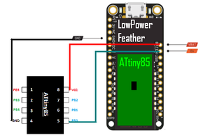
 k-angelis
 Jan Waclawek