 SimpleTronic
Quick Tour Video:
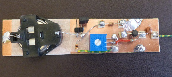
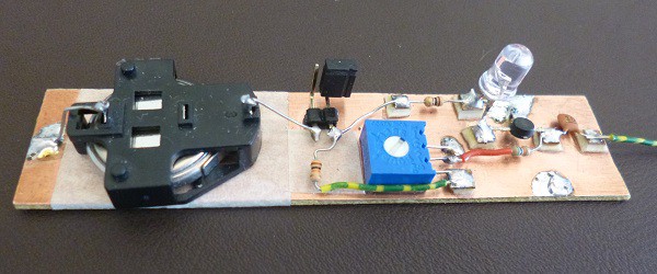
Circuit Diagram:
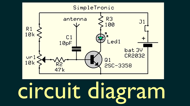
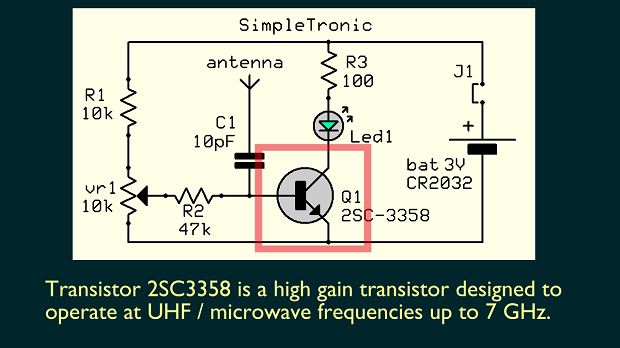
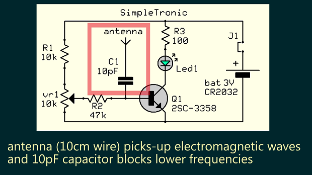
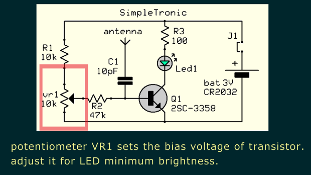
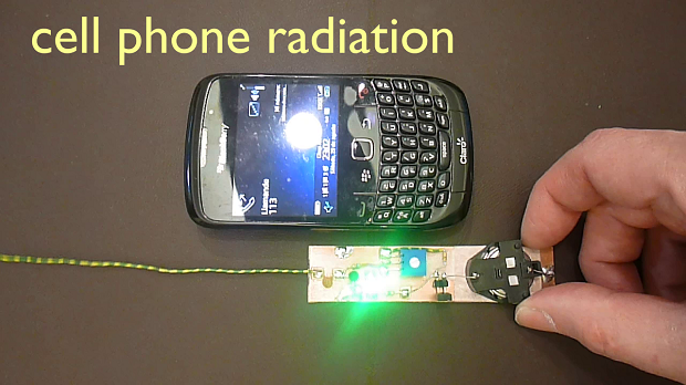
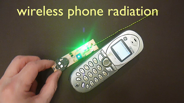
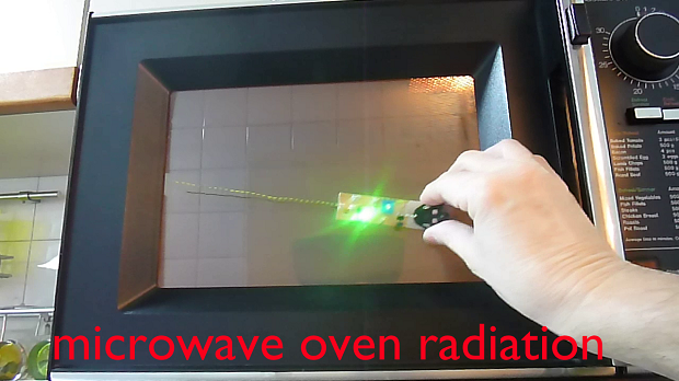
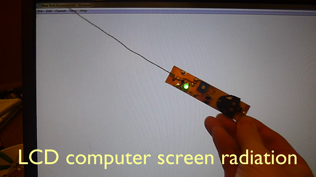
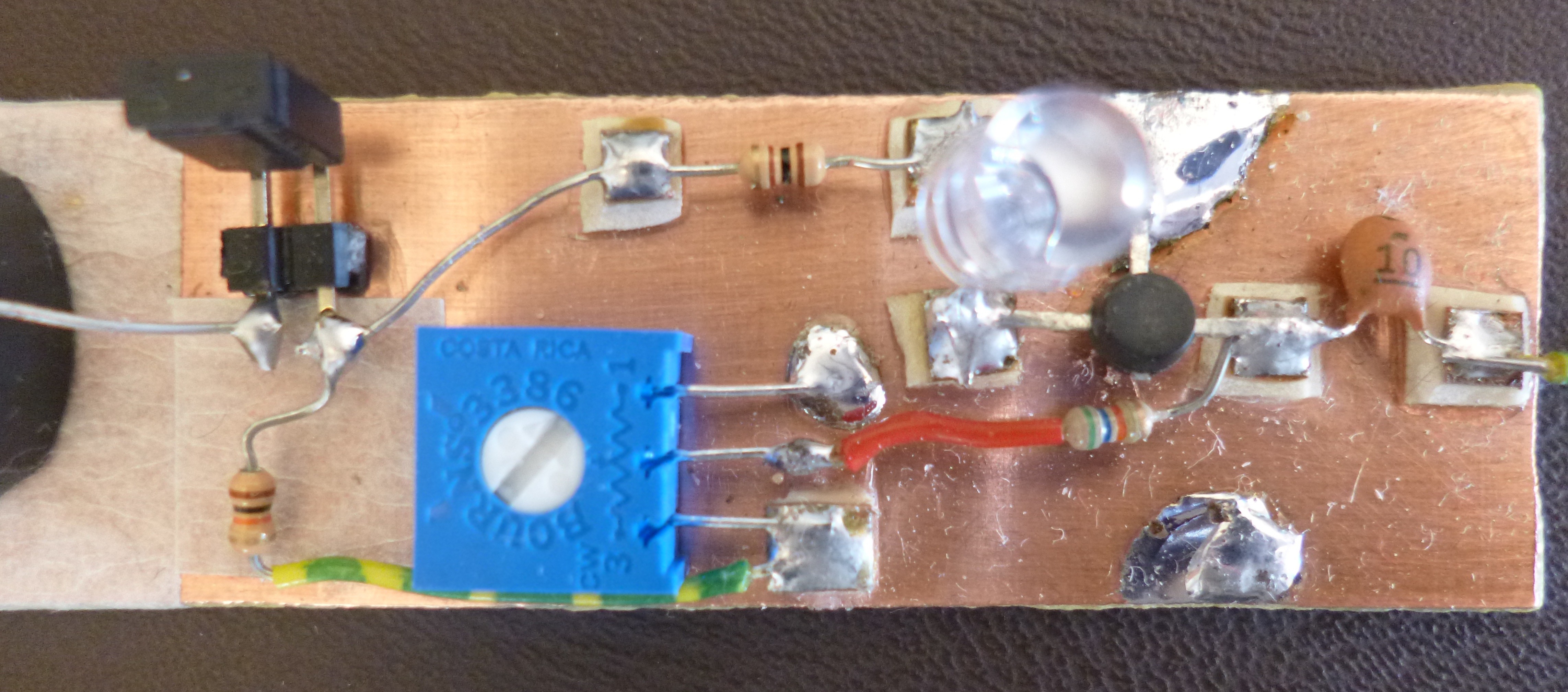
Circuit is an ultrahigh frequency (UHF) / microwave broadband amplifier. Transistor 2SC3358 is a high gain transistor designed for operating at frequencies up to 7GHz (7000 MHz). J1 (jumper or header pins) is the power switch. Potentiometer vr1 sets the bias voltage of transistor Q1 . It should be calibrated for minimum LED brightness with no RF radiation source close to antenna.
Circuit at Work:
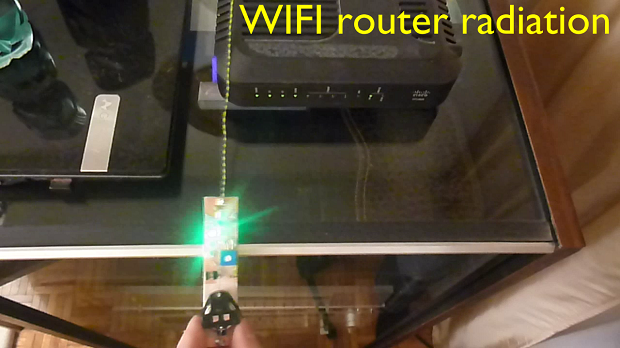
Use the circuit to find nodes in standing waves:
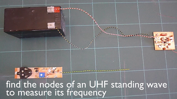
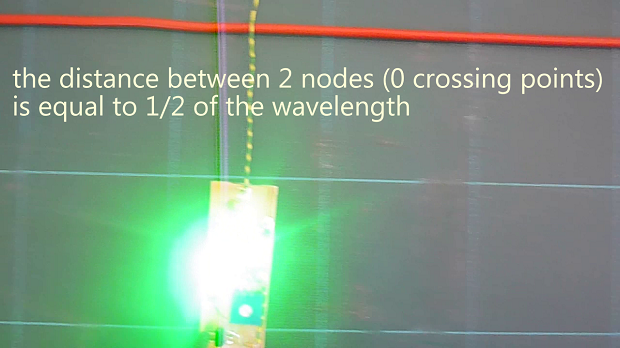
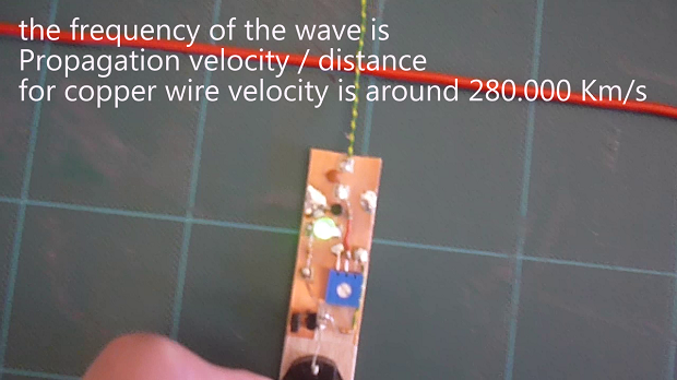
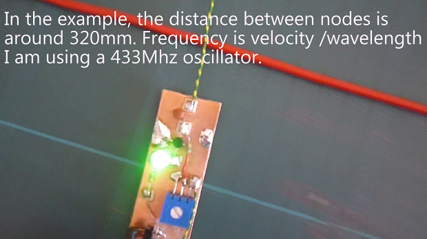
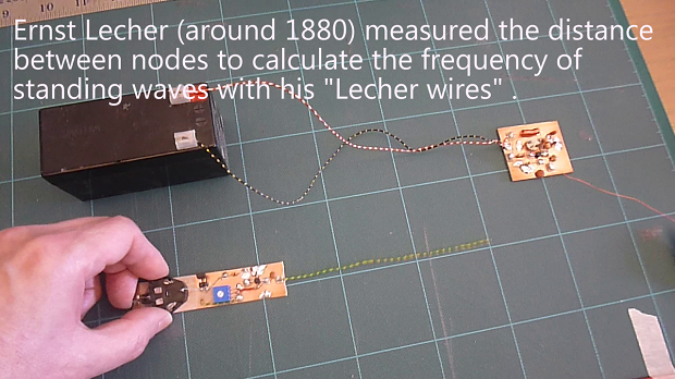
Ernst Lecher(1856-1926 ) measured the distance between adjacent nodes of a standing wave to calculate the frequency with his "Lecher Wires". https://en.wikipedia.org/wiki/Lecher_lines . In a similar way we can measure the frequency of our oscillator by finding the nodes sliding the sniffer antenna over a wire connected to the oscillator out. LED will be dark over the nodes. The distance between 2 nodes is equal to 1/2 wavelength. Frequency is the propagation speed divided by wavelength. For copper wire speed is around 280,000 Km/second. We could also measure the 60 HzAC line frequency with this method, but nodes will be 2350Km apart! . (wavelength: 4700Km).
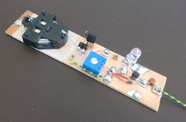
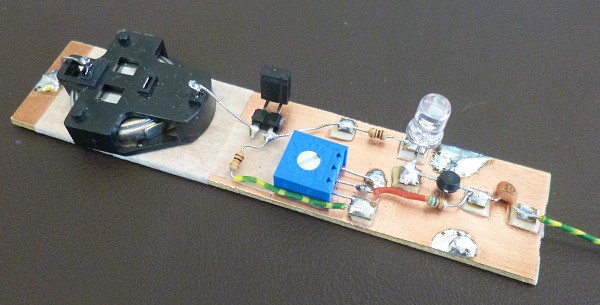
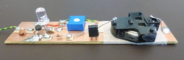
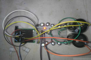
Project build images:
Circuit is built on a single sided copper-clad board using the MANHATTAN style construction.
 Electroniclovers123
 nbreakfast
 Andrea Console
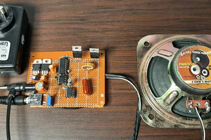
Hi! I would like to reproduce you RF sniffer circuit "as is" but having a hard time at finding the 2SC-3358 transistor, do you have a couple of suggestions as replacement ?
I looked for an equivalent with the keywords "hign gain UHF transistor" and I narrowed the results to the BFG 195 ou 196 but the packaging being different, I don'td feel at ease to not use an "exact equivalent".
Thank you for sharing you work