 Christoph Tack
Implementation details
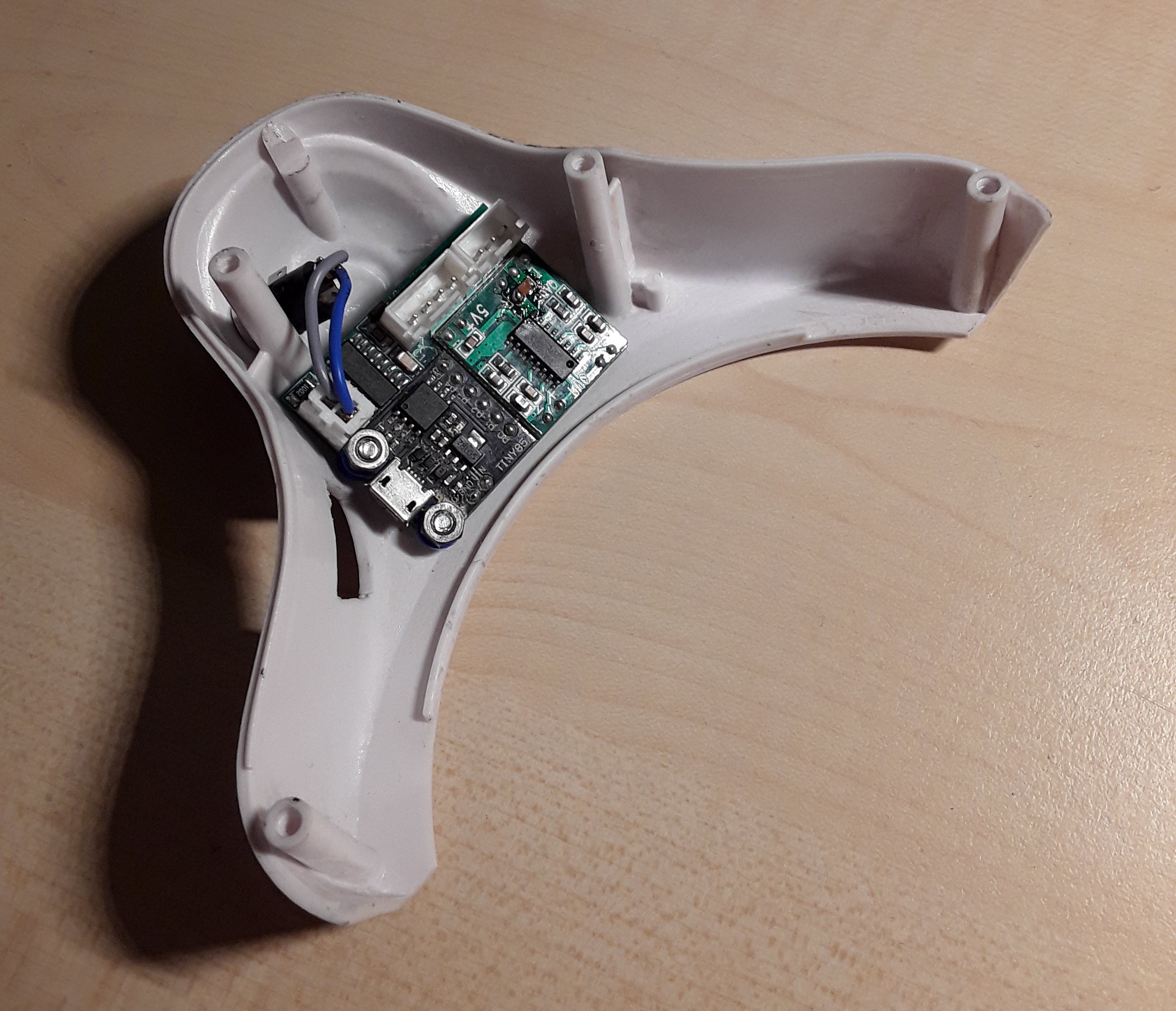
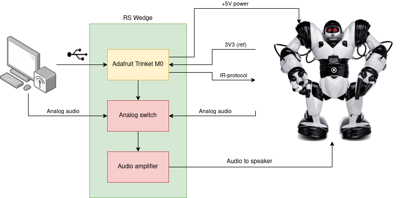
Power
The Robosapien was originally powered by four 1.5V size "D" cells, two in each foot. The weight in the foot is needed for stability during walking. If no weight is placed in the feet, the Robosapien will fall over during walking. The weight of a "D"-cell varies from 135g-200g, depending on battery chemistry and amp-rating.
The robot will now be powered from 5V USB. The connection can be made as follows:
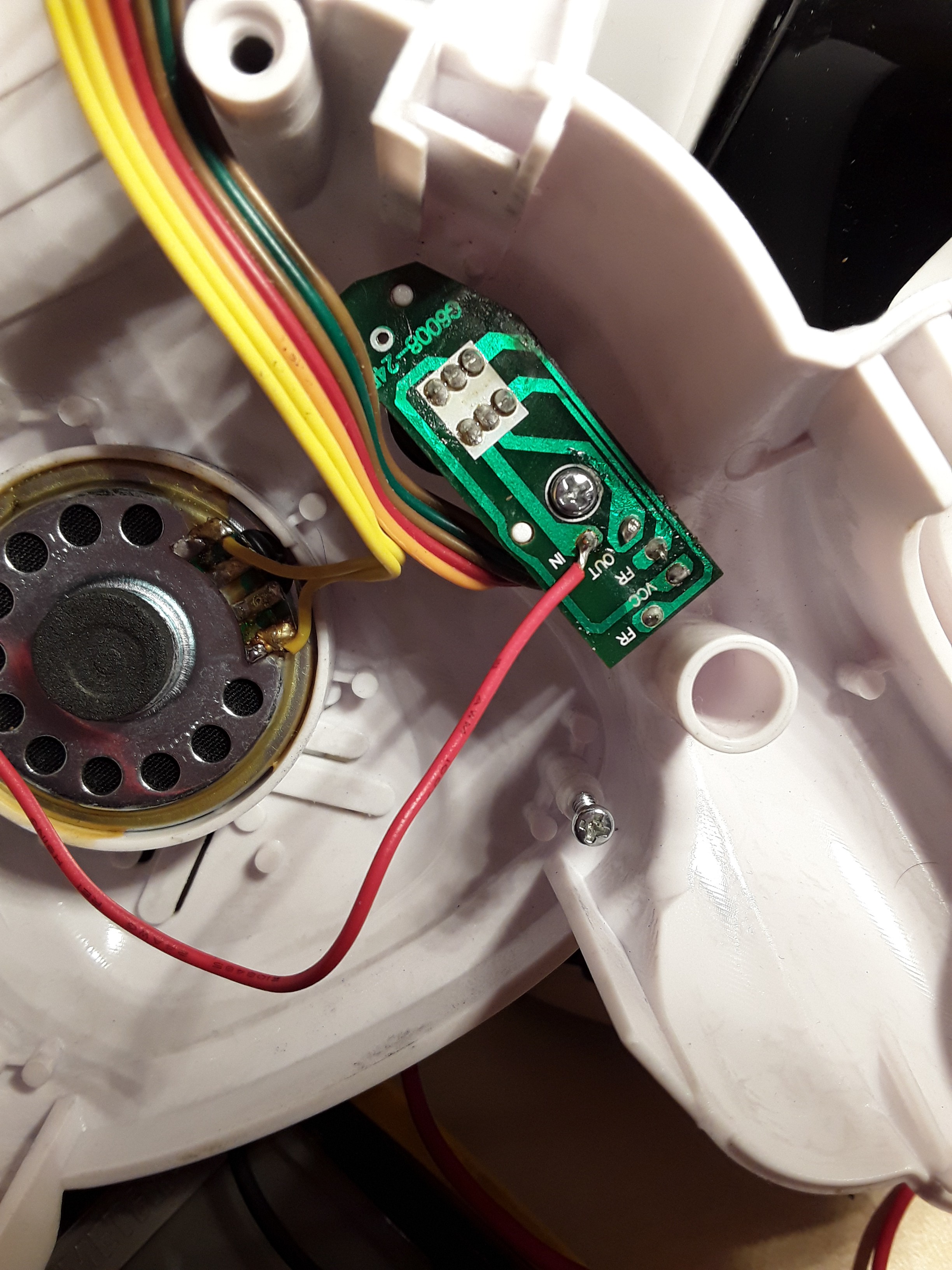
- Connector marked "L-SW-GND-C" on the main-PCB:
- use "GND" as USB-GND
- "C" connected the batteries on the left foot with the ones in the right foot, it can be disconnected now.
- On/off switch panel on the back plate : solder 5V from Digistump to "IN" on switch PCB.
By making the connections in this way, the power button on the back will still be functional. VCC = supply voltage for most of the circuitry = 3.3V. U1 on the main PCB generates VCC from VDD. VDD = supply voltage for motor driver and speaker = 5V.
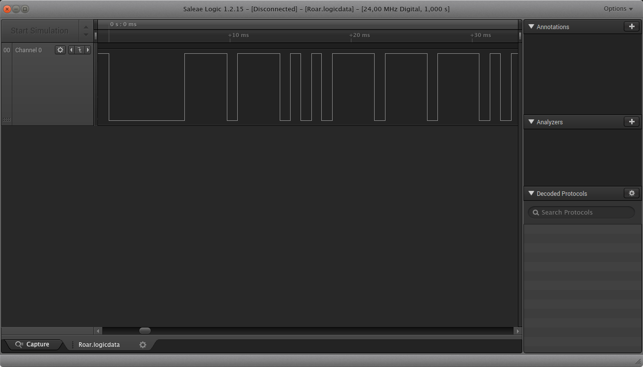
IROUT electrical connection
The IROUT-signal on the main PCB is 3V3-logic. The Digistump is 5V-logic. Care must also be taken to avoid latchup when the Robosapien is powered off while the Digistump is on.
IROUT has been pulled up to VCC with a 1K-resistor. A BAT46W-schottky diode is used to connect to the Digistump. The anode of the BAT46WJ is connected to IROUT. The cathode is connected to the Digistump GPIO (i.e. the P0-pin).
The IROUT-waveforms look ok.
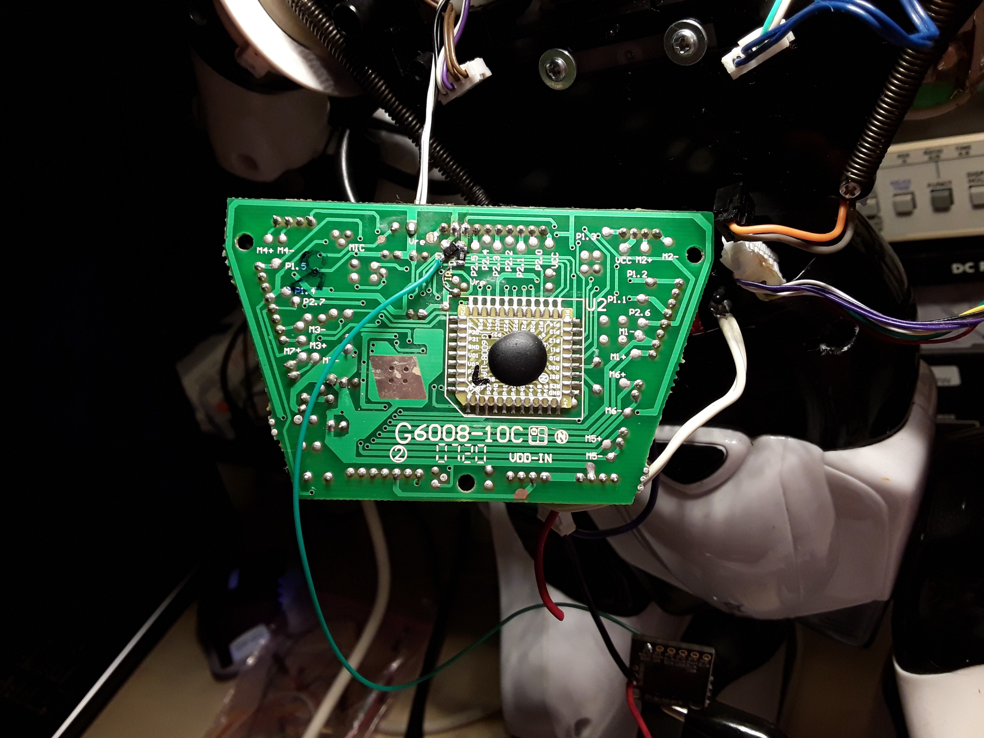
Once this worked, I designed the PCB that gets mounted into the Robosapien's leg. The diode is incorporated into that PCB so it's no longer needed to solder one on the Robosapien's main board.
Python
To get the events from the calendar, either pyexchange is used for on-premises servers or exchangelib for Microsoft 365.
The TTS-engine has also been replaced by a python library, enabling migration to Windows platforms.


 Lithium ION
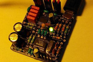
 Andreas Dahlberg
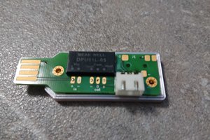
 Christoph
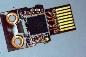
 Sam Ettinger