clewsy
Rev_2
In August 2020, with some time on my hands I finally got around to a second revision of this project. Improvements include:
- Hardware:
- Pull-ups on I2C SDA and CLK lines.
- Drive relay with a transistor instead of direct from IO.
- Add flyback diode protection to relay coil.
- Smaller transformer.
- Smaller relay.
- Switch to SMD where possible.
- Two-sided PCB (have it fabricated instead of etching).
- Switch buttons from mushy panel-mount to tactile SMD.
- Balanced caps for the 32.768kHz crystal.
- Put grind button LED on a PWM output.
- Firmware:
- Switch from C to C++.
- New OLED driver (change from SPI SSD1306 to IIC SH1106 controller).
- Pulse/fade effect for grind button LED.
- Ability to cancel a grind once started.
- Remember selected preset after a power-cycle.
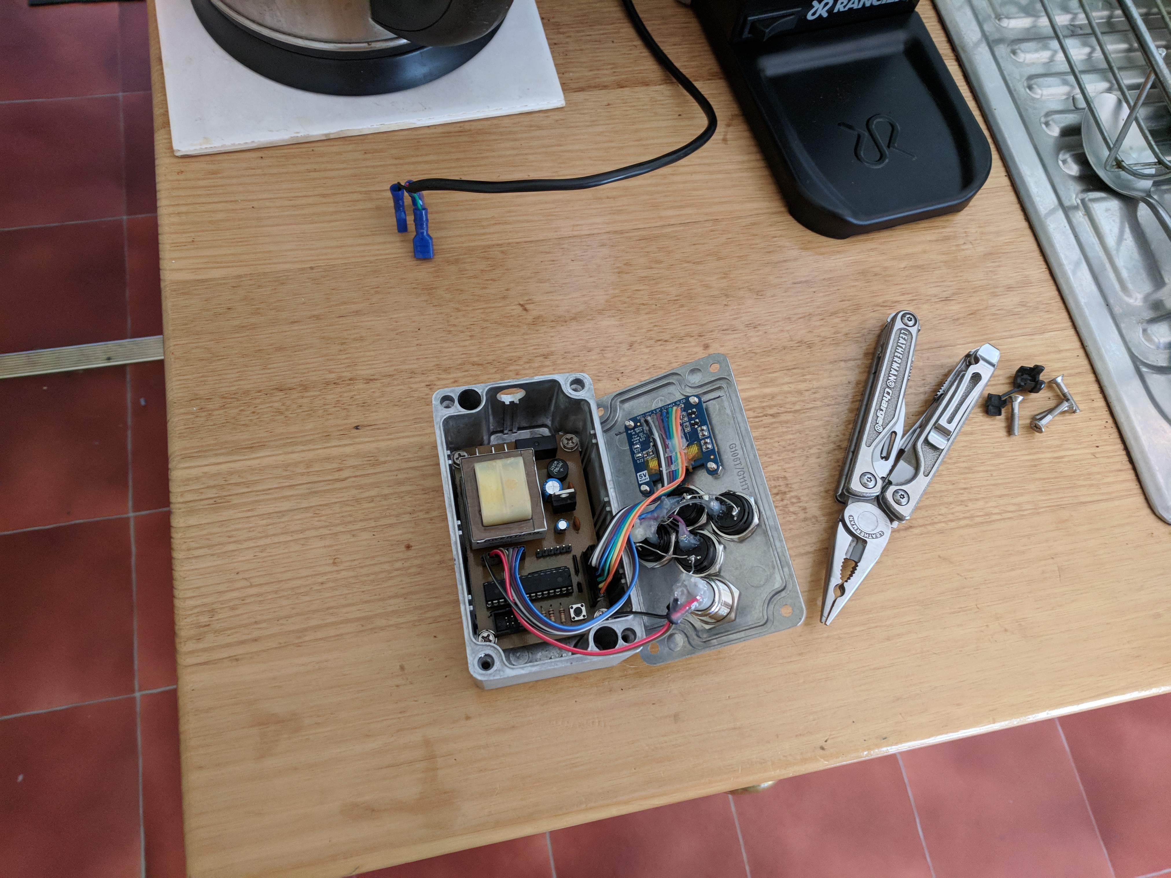
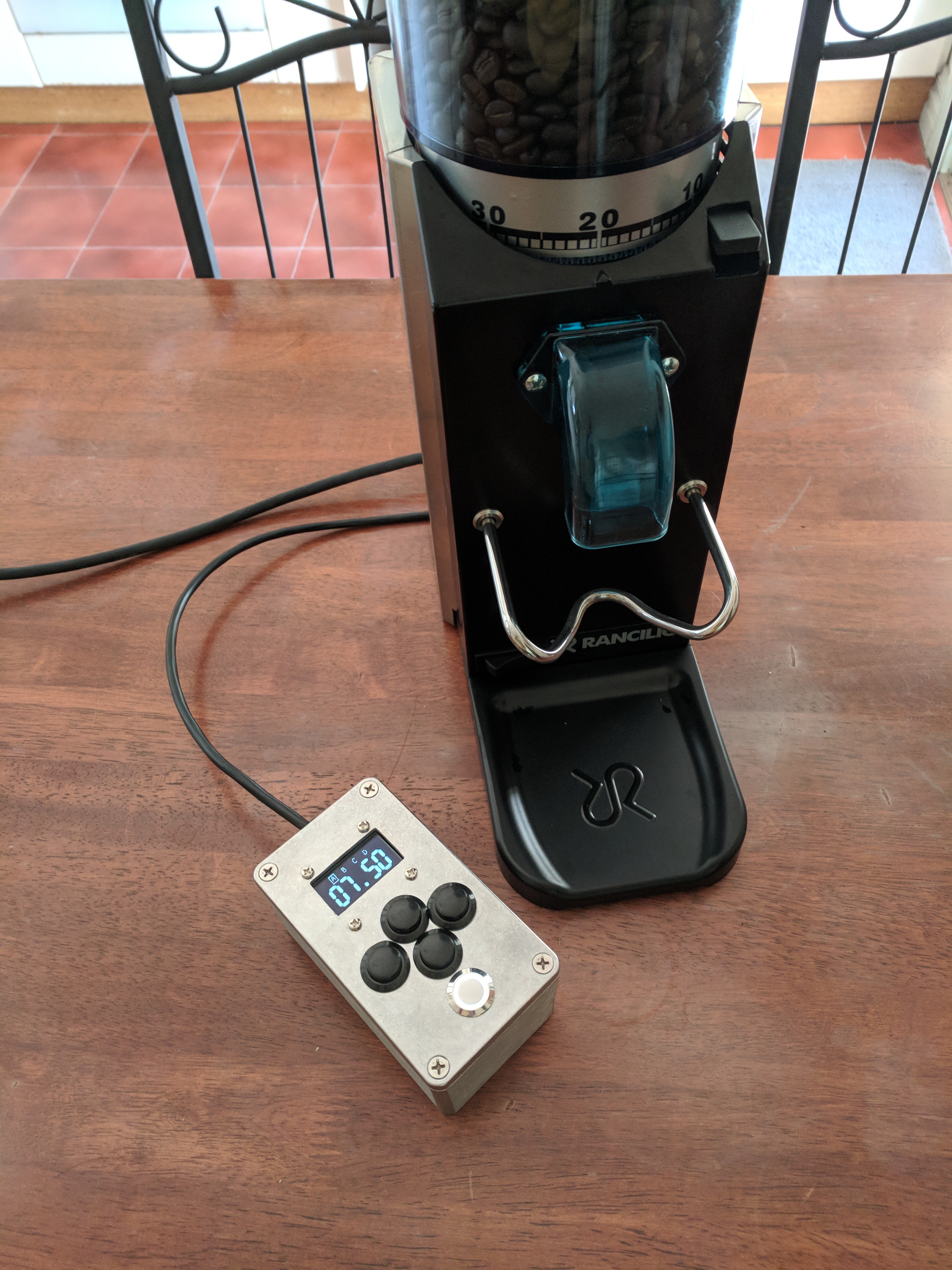
Grinder Tether
A three-core cable is required to tether the grinder_timer to the coffee grinder. The cores are required for power (active, neutral) and to actually switch on the grinder (motor). The tether cable is connected at both ends via spade connectors. Within the grinder, the spade connectors splice into existing spade connections with no modifications required. The cable is run through the same grommet as the grinder's AC supply cable. There is no permanent modification to the grinder required.
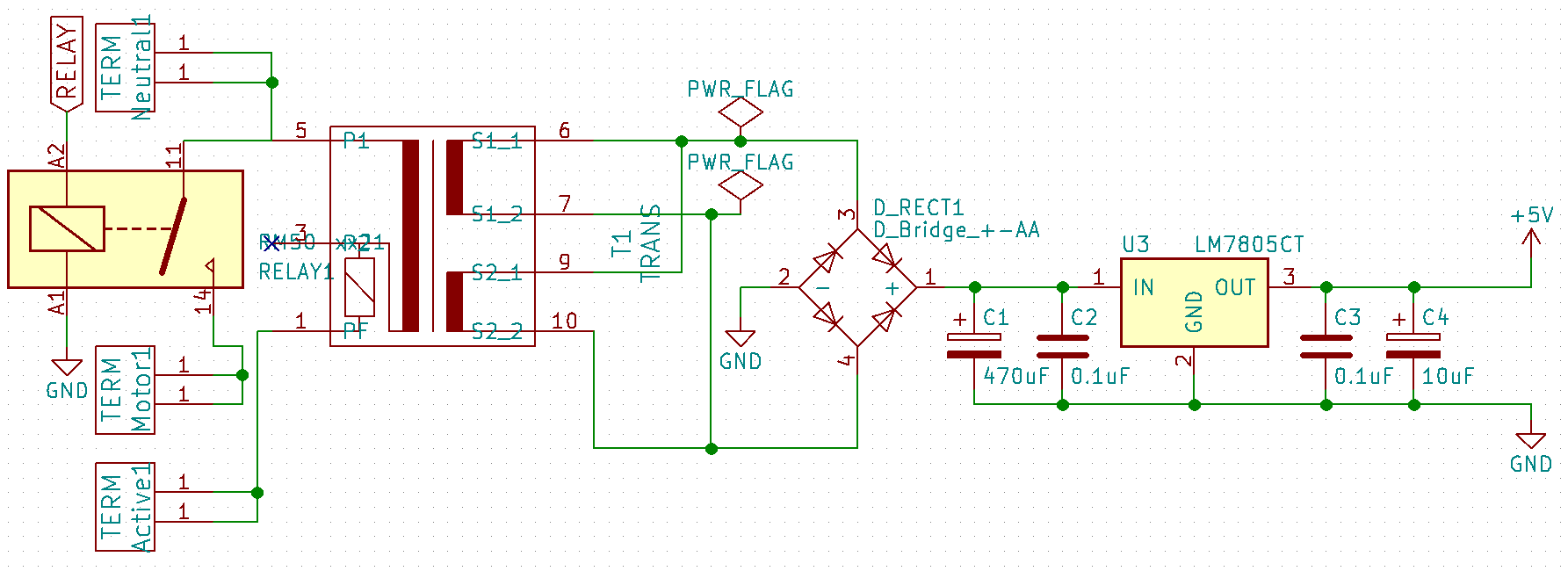
Power
The grinder_timer takes power from the coffee grinder. Since the grinder is a simple AC circuit, the grinder_timer had to include power transformation/rectification/regulation to provide 5V for the other components. The power sub-circuit uses basic components to provide 5V to the AVR and other components.
- Transformer 240VAC/6VAC x2 @ 0.25A (secondary coils connected in parallel for 6VAC at 0.5A).
- Bridge Rectifier.
- Filter Capacitors - 470uF, 10uF, 2x 0.1uF.
- Voltage regulator LM7805.
- Relay 5A/250VAC.
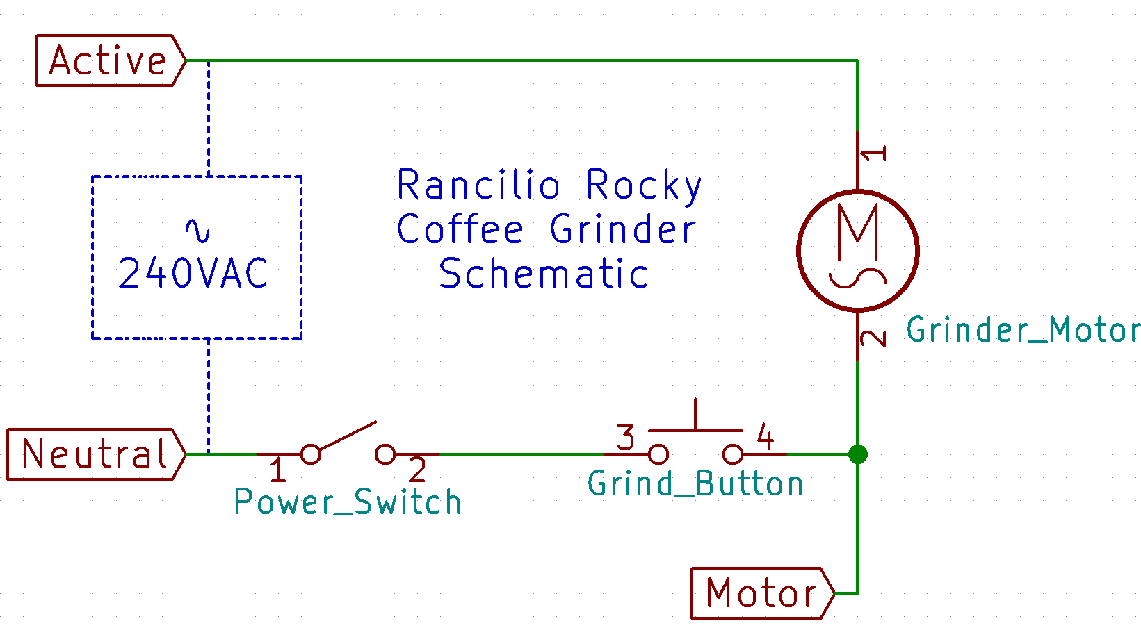
Motor Control
The grinder motor is switched on/off by grinder_timer via a relay. Closing the relay simply completes the neutral side of the grinder motor circuit.
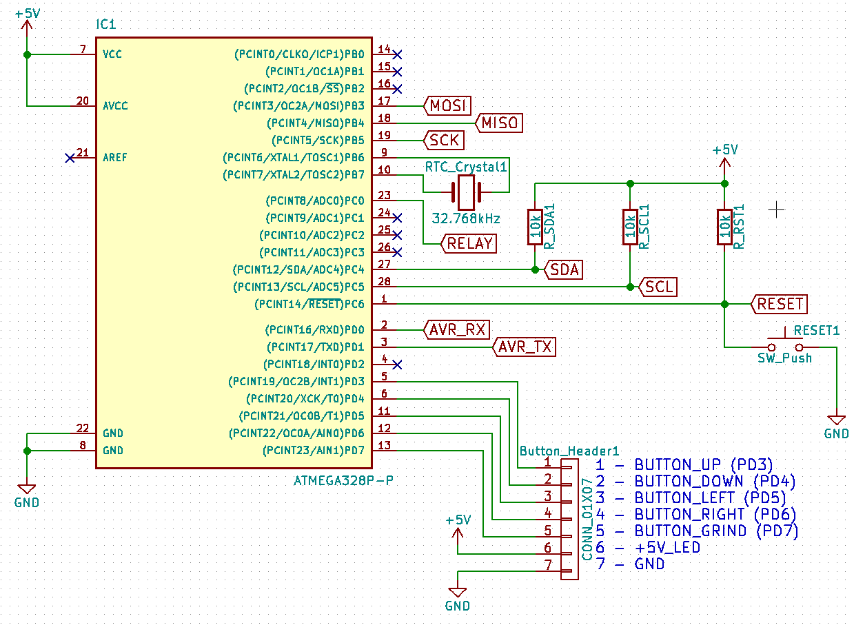
AVR Circuit
The main circuit is centred around an ATmega328p AVR micro. It is connected to pin headers for connecting the buttons and a USB/Serial adapter. Another pin header is for I2C control of the OLED and includes pull-up resistors on the clock and data lines.. There's a six-pin ISP header for programming. I wanted the countdown timer to be reasonably accurate so there is a 32.768kHz crystal connected so as to implement an RTC (real-time clock) with the AVR.
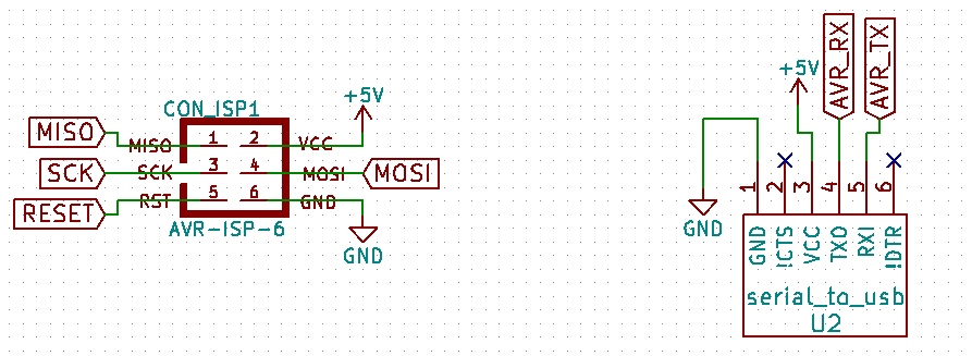
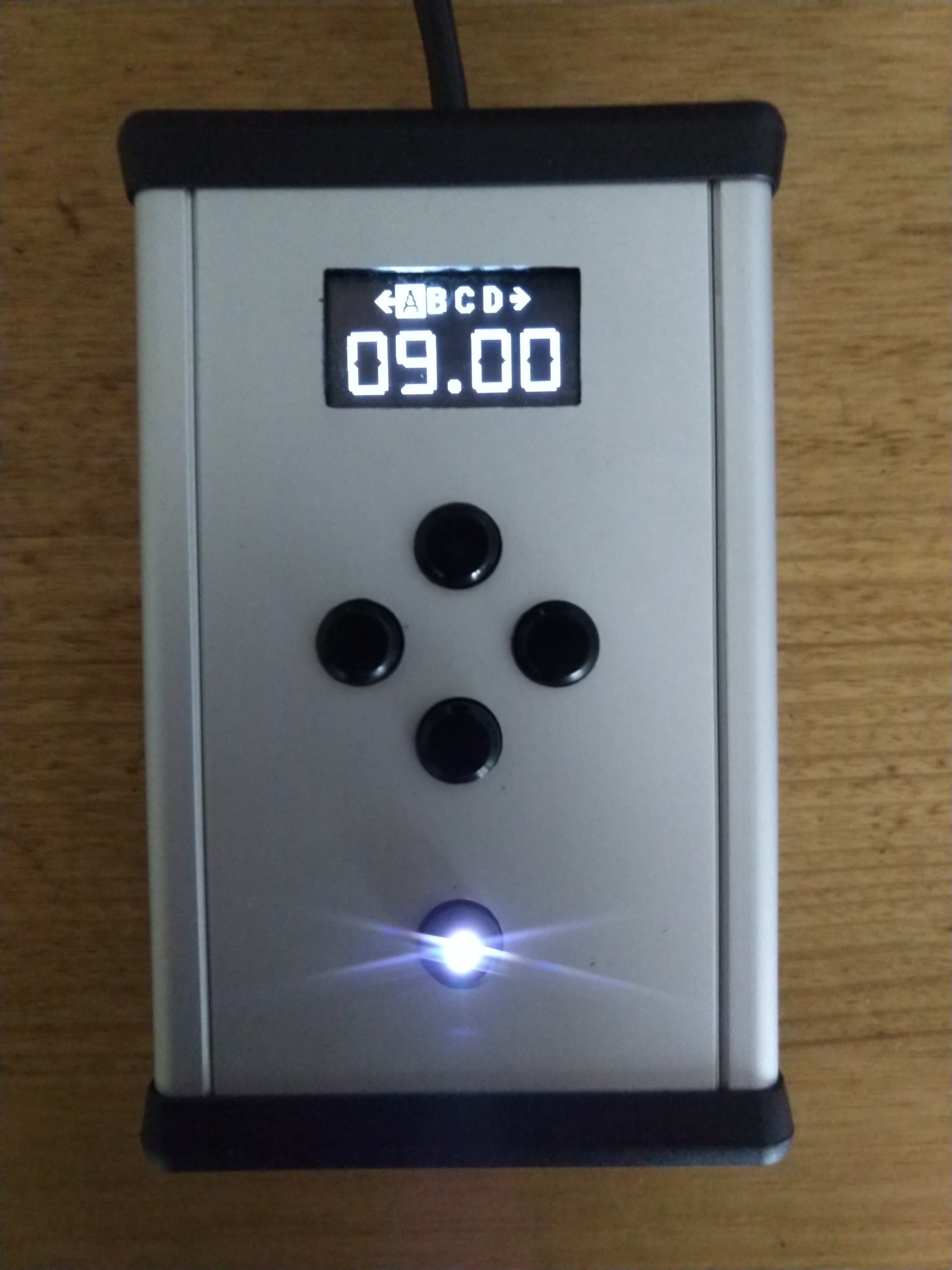
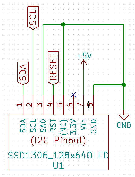
OLED Module
The display is a 128x64 pixel mon OLED driven by an SSD1306. It is controlled by the AVR's I2C (TWI) peripheral. The module is physically connected via a pin header on the main circuit board.
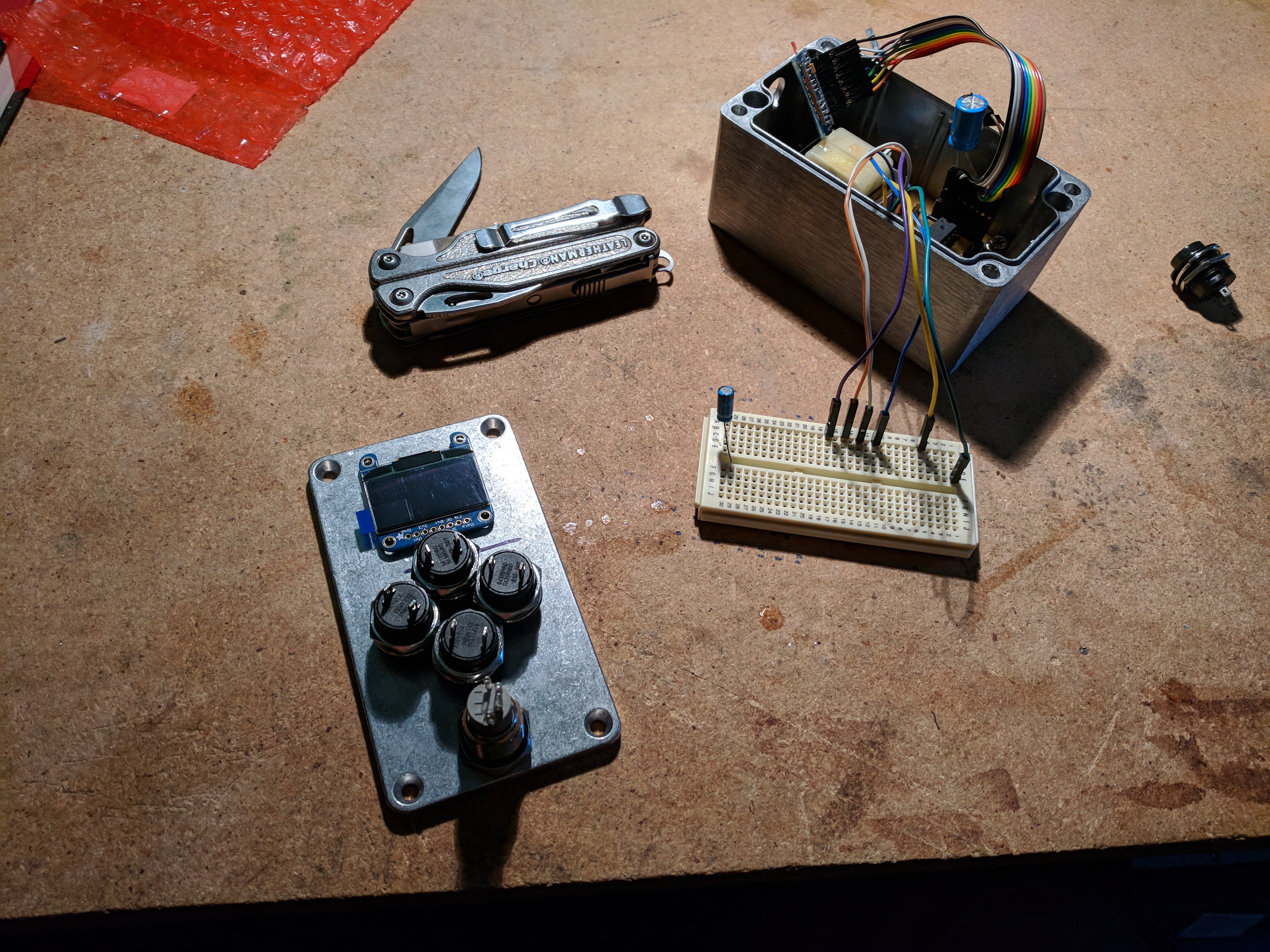
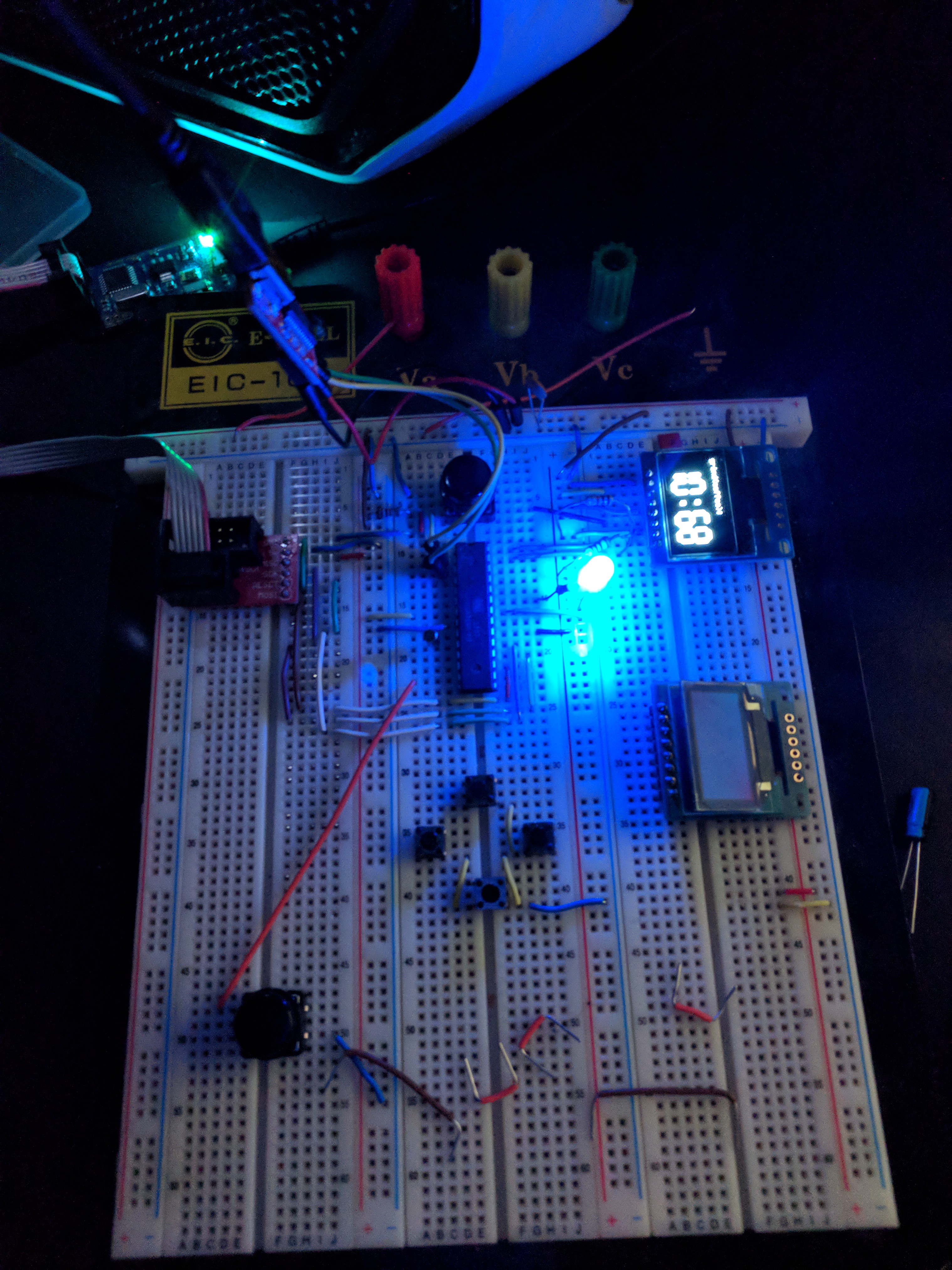
Prototype Circuit
I developed the prototype of the electronics on a bread-board simultaneously with the schematic CAD.
Code
Early development stages of the code was written exclusively with vim from the terminal (terminator). However I had read about Atom and decided to try it out so at some point in development I switched over.
The code is all interrupt driven. Pushing any button runs the pin-change interrupt that checks which button and performs the appropriate action.
The grind button enables the timer/counter 2 peripheral which is set up to use the external 32.768kHz crystal. This is the timer that actually counts down the desired duration. This could have been done with an internal oscillator, but I wanted to learn about using the AVR as an RTC for more accurate and consistent timing.
The AVR's internal eeprom is used so that the stored presets survive a powercycle.
One trick I missed with the OLED module is the requirement to toggle the reset line as part of a start-up sequence at boot (datasheet included on github repo). I simply tied the reset line to the AVR's reset line. I eventually found this was causing issues at power-up because the oled reset is supposed to be toggled a minimum duration after the oled power stabilises. Ideally, this would be done with code using one of the AVR's GPIO pins tied to the OLED's reset pin. The workaround I figured out was a capacitor across the OLED's reset pin with enough capacitance so that on power-up there is effectively a delay setting the reset line high while the capacitor charges up. This is a bit of a bodge but seems to work and has the benefit of not requiring an additional GPIO pin. However, if I need to iterate, the next circuit design would probably include AVR control of the OLED's reset line.
I designed a seven-segment-style font for the timer display. This design was done using a spreadsheet which is included in the reference material on the repo. Each digit is 24x48 pixels.
Circuit Design
The schematic and PCB layout were designed with KiCad. Prior to this project my only circuit CAD experience was with eagle. I used this project to familiarise myself with the open source alternative. All the KiCad project files are included in the github repo.
The PCB layout outer-dimensions was driven by the size of an aluminium enclosure I wanted to use. This enclosure was selected based on the most cumbersome component - the PCB mounted transformer.
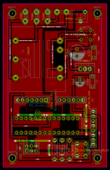
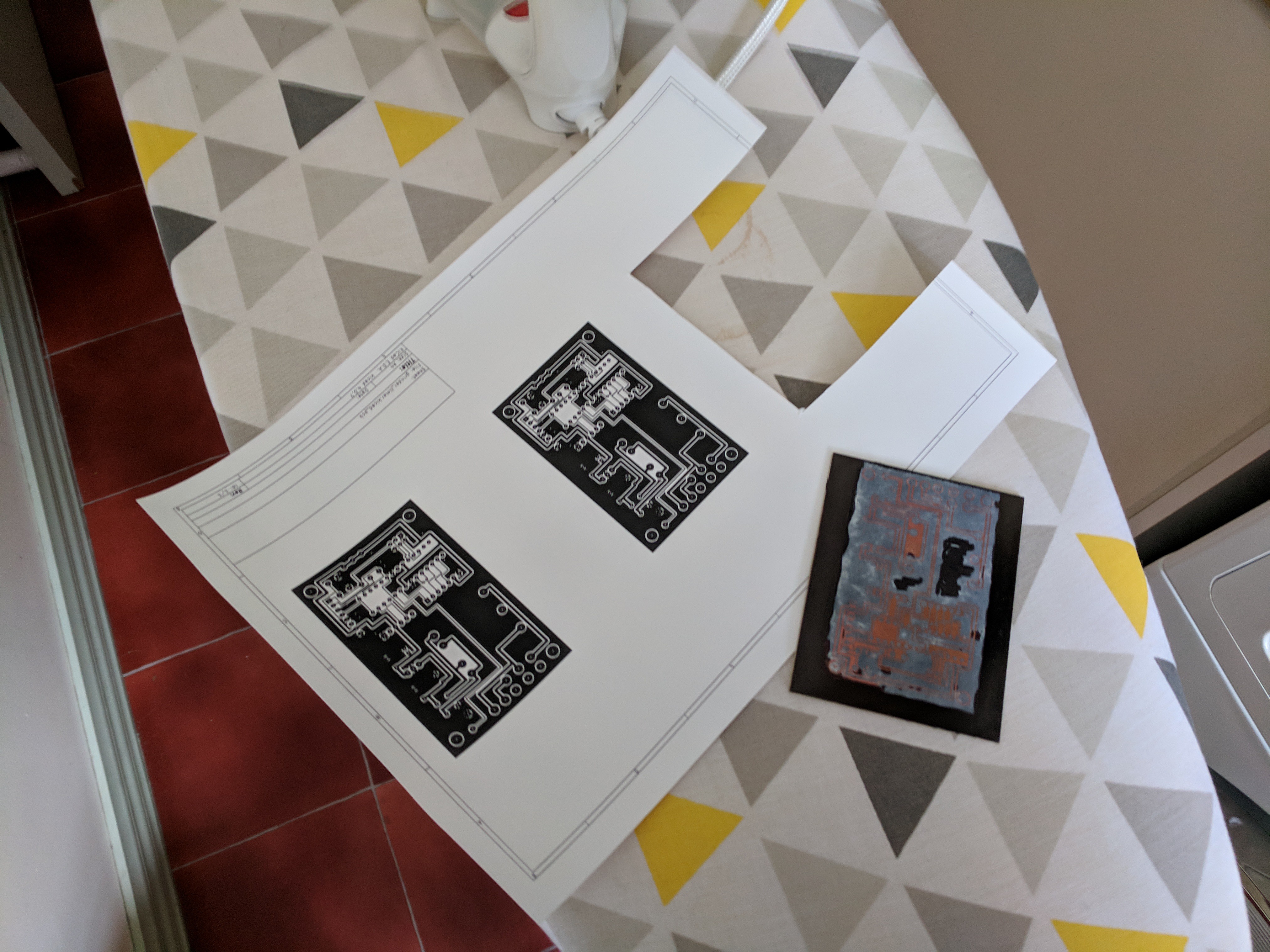
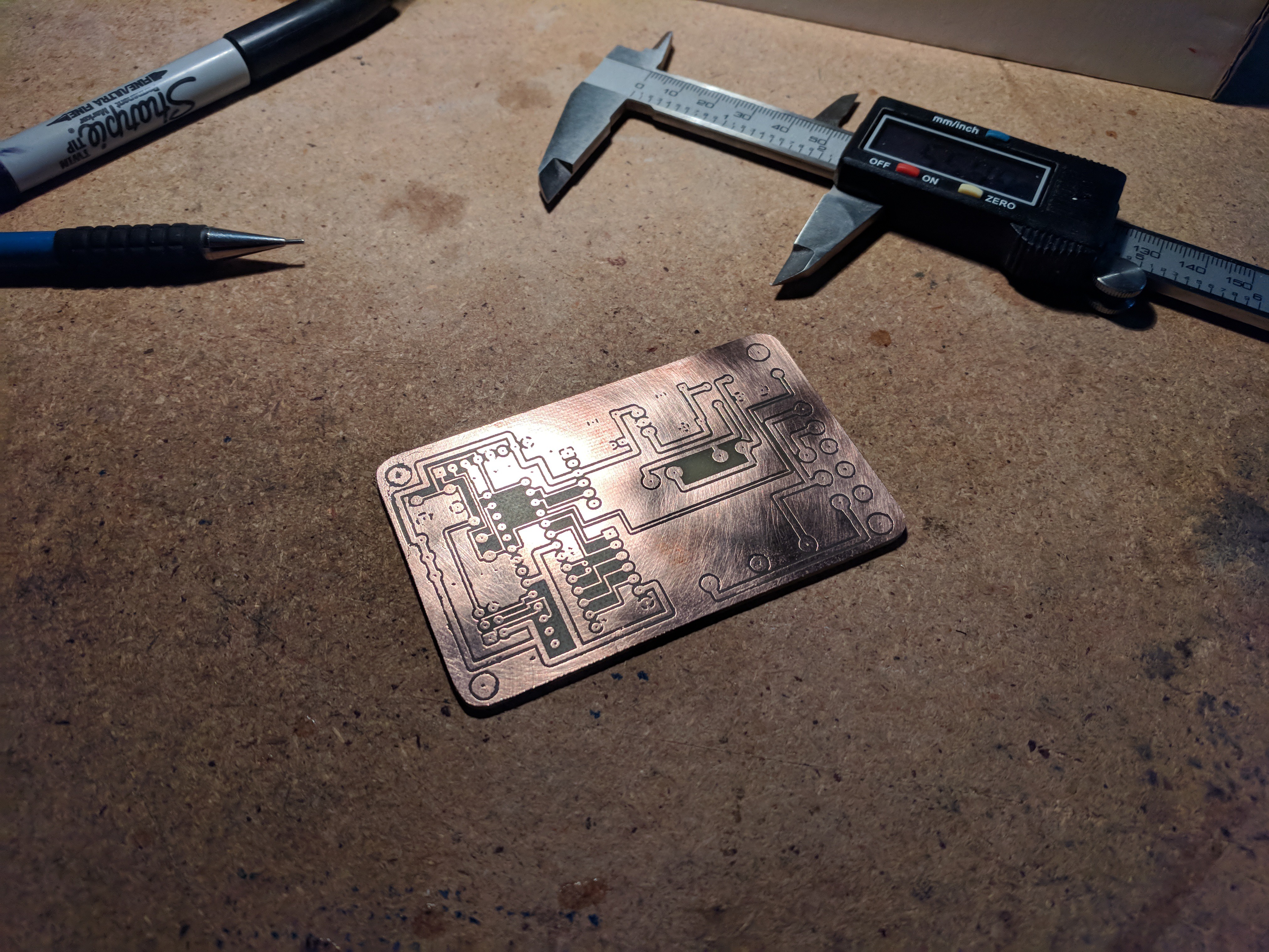
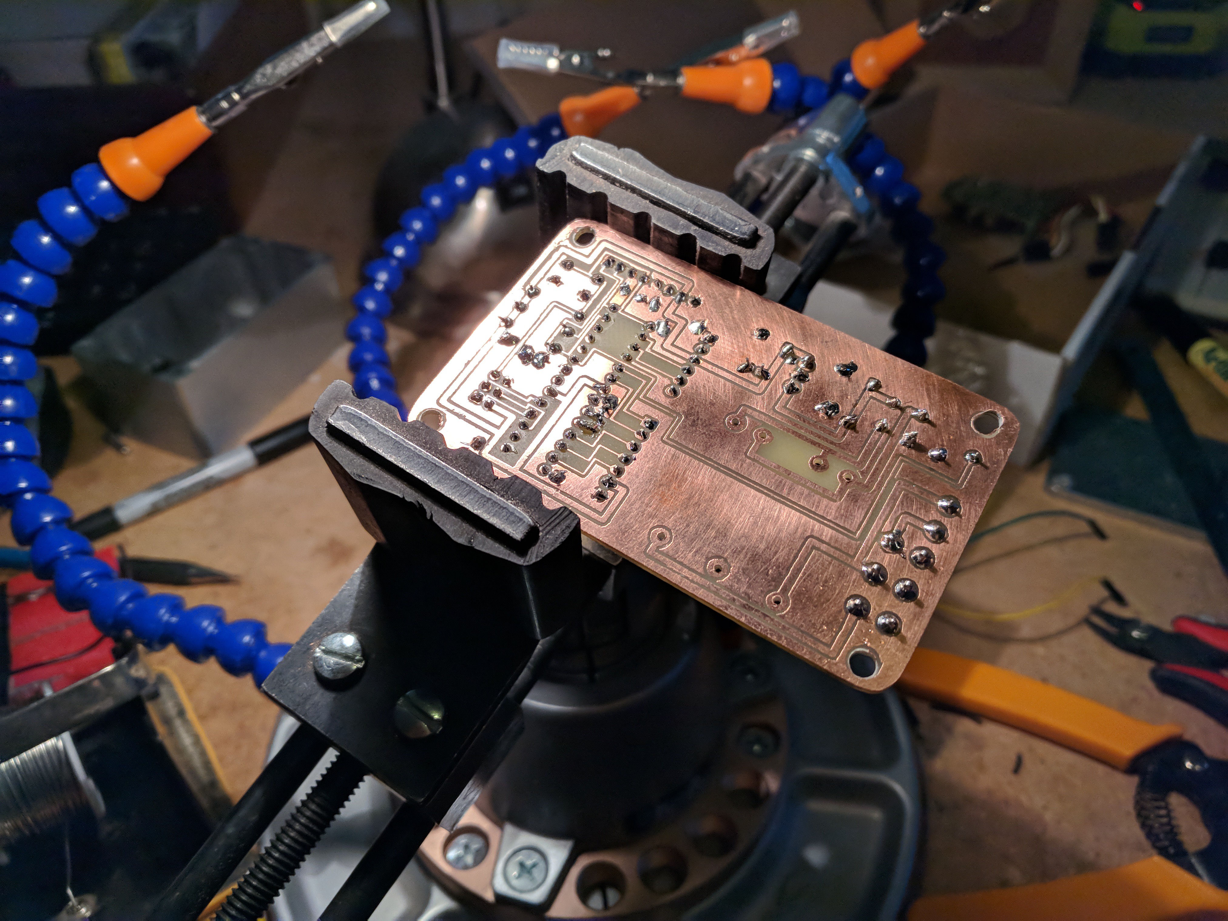
PCB Fabrication
I designed the PCB to be fabricated using the toner-transfer method a single-sided copper-clad board. After etching, I cut the board to size, drilled the holes and started populating.
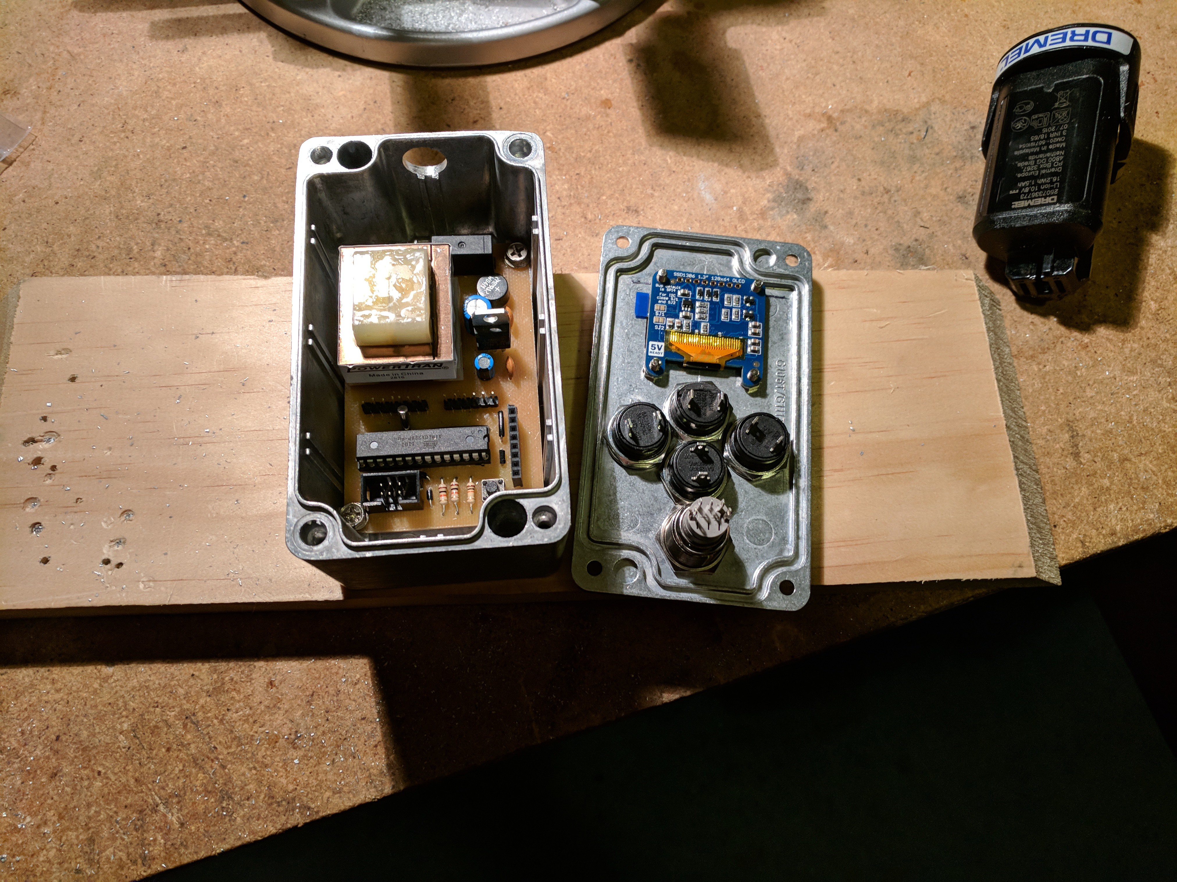
 Enclosure
The PCB was mounted within an aluminium enclosure. The lid was cut to mount the OLED and the five buttons, all of which connected to the PCB via headers. The tether cable connects to the PCB via spade connectors and runs through a hole (with grommet) through the enclosure. The other end of the tether cable runs through the existing power-cord grommet on the grinder and ties into the three connection points via 3-way spade terminal splices.