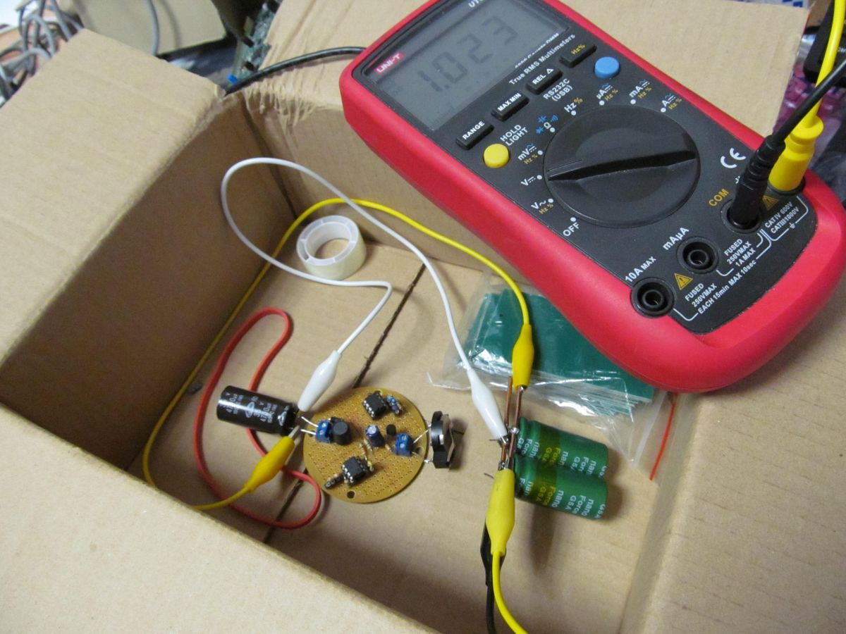
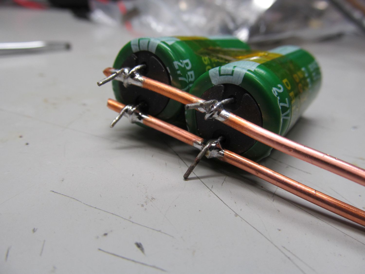
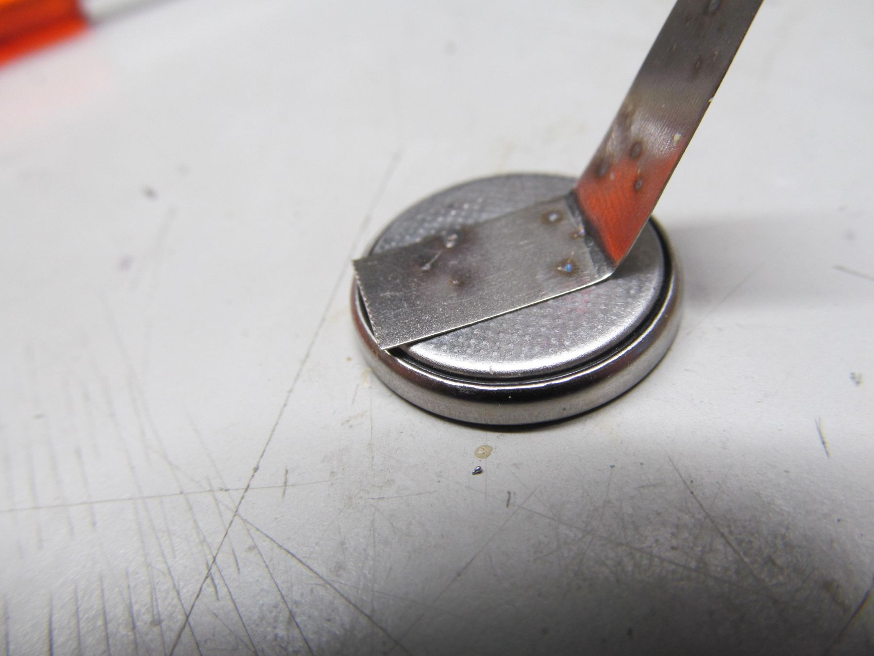
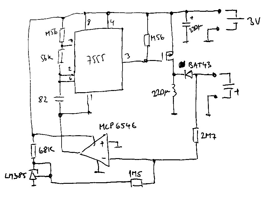
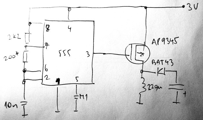
• Resume

    jaromir.sukuba01/08/2018 at 21:56 0 comments

    At beginning of this project I setup two goals - make spot welder for thin battery tabs and power it from CR2032 cell. Looks like I was able to fulfill both the points, as seen on previous project log.

    Needless to say, this project doesn't end up with particularly useful welder. Having to wait for day and half to make a few welds isn't terribly efficient way of doing this, but on the way I learned a few new things

    • Coin cells do contain surprising amount of energy
    • The energy isn't trivial to get out, especially when you are in hurry

    Those two facts were main limits between which the project oscillated. At one side I had to extract energy as slow as possible, to utilize the CR2032 cell as good as I can, on the other hand I had to charge fast, in order to not lose energy via capacitor self discharge. The charging circuit had to be of unusual type, drawing constant power from cell.

    Apart from that, this design was little exercise in simple analog design, with no microcontroller involved. 555 timer in its CMOS variant performed very well and with voltage reference and comparator (all of them being low-power parts) I achieved also goal of automatic charge termination and relatively low consumption (~30uA) after that. Current consumption is not the key factor of this project, as the coin cell here is to be depleted and its charge transformed into tiny bits of liquid metal in blink of an eye.

  • Charging done, sparks

    jaromir.sukuba01/08/2018 at 21:09 0 comments

    After som problems I mentioned in previous log, I made some minor tweaks. Charge termination worked perfectly again and in something like day and half worth of charging the capacitor was roughly at 2,65V, as seen on this graph of voltage versus time in minutes.

    What to do with charged capacitor? Discharge it!

  • First charging, almost there

    jaromir.sukuba12/19/2017 at 14:00 0 comments

    I put together two pieces tested separately in previous logs - capacitor bank and charger. I know the charger is able to charge smaller capacitor, as I know the 100F supercap si able to spot weld 0,12mm thick nickel strip to battery.

    Everything is powered by single CR2032 cell and voltage on supercap is monitored by logging DMM. I adjusted the 2M7 resistor from this log to get higher value. I did a quick math and inserted 1,2MOhm resistor in place.

    When I returned to place, I found out the capacitor isn't much charged, battery is happily at 2,9V, looking at voltage log revealed what went wrong,

    Ignore the dropout at roughly 100 minute mark - it was loose probe. The capacitor charged nicely to approximately 0,97V, then it stopped. The change was quite abrupt and voltage didn't fall much since then, so the capacitor was trickle charged, because the charger decided to do so.

    In order for the charger to stop charging, the voltage on inverting pin of comparator has to be equal to zero (voltage on non-inverting input). This happens when voltage on the two resistor is divided exactly in ratio of their resistances, so

    where Ru is upper resistor in divider (2,7M in my first example) Rb is bottom resistor (1,5M in my first example) Vc is voltage on capacitor and Vr is reference voltage, 1,23V here.

    Solving for Ru 1,2M gives me voltage about 0,98V, what seems to be exactly what I measured. To get to around 2,6V, I need to set the resistor to 3,2MOhm, so that 1,2M figure was apparently brain fart. So now I lost 20 hours of time, but the charger seems to work exactly as expected and works per my commands (not my intentions, though).

    Notice the voltage during "trickle charging"

    Every time the voltage decreased under ~ 0,97V, comparator noticed and charger started charging, action stopped at ~ 0,975V. Capacitor discharged slowly (mostly due to its own leakage), so the frequency of charging events is proportional to the discharge rate. You can see the discharge rate apparently decreased over time, this goes together with datasheet values of discharge specified to be 0,16mA after 72 hours for 50F capacitors, suggesting the value decreases over time. Interestingly enough, I measured value ~ 1,7uA (two orders of magnitude) for both of them at 0,97V after 19 hours from start of charging at room temperature.

    Now I'm continuing the charging with the same CR2032 cell and feedback resistor of 3,2MOhm, voltage is around 1,13V at the time of writing this sentence.

  • Supercaps delivered, first welds

    jaromir.sukuba12/14/2017 at 09:17 5 comments

    I received two 50F supercaps and didn't hesitate too long to do some torture to them. To get some more angry pixies, I wired them both in paralell, using 2,5mm thick copper wire.

    As I was too lazy to wait for my charger from previous logs, I hooked it to laboratory power supply via crocodile clips, set to 2,6V and 2,5A current limit, waiting a while to charge up. After charging I disconnected the clips and shortly pressed the two copper electrodes against nickel strip placed on discharged CR2032 cell. I think I'm going to have some more depleted cells in near future.

    Capacitor discharged part of its charge with tiny spark, I was able to do three welds from single charge. Here is the cell after pull-test.

    The bonding seems to be reasonably strong.

    So, now I can try to charge it from my charger and try to make some welder prototype. I also thought of controlling the discharge via MOSFETs, to get better weld repeatability.

  • Charging efficiency

    jaromir.sukuba12/10/2017 at 10:57 1 comment

    While my supercaps are ordered, but still not delivered, I made a few experiments with charging "classic" 4,7mF capacitor.

    I added 10Ohm resistor in series with my laboratory power supply set to 3V to roughly "emulate" CR2032 cell, but my primary goal was to get current sense resistor to obtain somehow more accurate power measurements. I started with discharged capacitor, turned the supply on, and waited for scope to trigger. This is how the measurement looks like.

    The pink trace is voltage on transistor gate, yellow is voltage on sense resistor (here -60mV means 6mA of current) and blue is voltage on capacitor. Notice how the comparator turned off the charging at preset 2,2V, with occasional charge impulses to cover self-discharge.

    The capacitor charges in 1,35s, with average current of 6,6mA, that is approximately 26mJ of energy, while there is approximately 10mJ of energy in the capacitor, yielding 40% efficiency. Not exactly totally bad, but not brilliant either. The first suspect was BAT43 diode - I assumed it's OK for this purpose (low current, low leakage), but it seems to be not the case, with high current spikes charging the capacitor. Higher power diodes do have lower voltage drop, but also higher leakage current, specified up to 1mA or so - usually at maximal voltage and elevated temperature, both being rough conditions for leakage. I measured dozen of randomly chosen SB130 diodes and all of them were in region of 1-2uA of leakage at 3V, so with fingers crossed I can be happy with its leakage properties. Interesting enough, the SB130 diode improved efficiency of the converter to approximately 54%, so I'm more OK-ish with that. The protoboard isn't particularly great for impulse circuits, so moving the project to proper PCB can increase the efficiency a bit too.

    Now I'm really curious about the supercapacitors.

  • Charger seems to work now

    jaromir.sukuba12/07/2017 at 20:23 2 comments

    I took an hour this afternoon and put together somehow extended version of the converter, and moved from breadboard to protoboard.

    In addition to previous simple DC/DC converter, this one has five components added

    When turned on, voltage on LM385 is 1,24V, voltage on cap to be charged is zero, MCP6546 comparator "sees" more positive voltage on noninverting input, so its open-drain output is low. 7555 timer can oscillate, voltage on capacitor stars to rise; being more and more negative against circuit ground.

    When voltage on LM385 versus voltage on capacitor is in ratio 1,5/2,7 - given by resistors on inverting comparator input - the voltages on both comparator inputs get equal and comparator output starts to rise up. Power supply of 7555 is cut off, transistor stay closed and circuit takes as little power as possible, mostly by current via LM385; being set to 25uA at 3V. As soon as capacitor discharges a bit, voltage on inverting comparator input rises, its output goes low, 7555 starts oscillating again and charging the capacitor again.

    With components as per schematics, voltage on capacitor is stabilized at roughly 2,2V. Slightly lower than needed, but OK for experiments. Now I need to measure its efficiency and connect an actual supercap. Flux capacitor is to be added later.

  • Now it's proper hack!

    jaromir.sukuba12/06/2017 at 22:02 3 comments

    In the previous log I touched the surface of capacitor charging problem. I can't connect the battery to capacitor directly from two reasons:

    1. The battery has high internal resistance, capacitor is discharged at the beginning, thus acting as short circuit, overloading battery.
    2. If I even had battery with zero internal resistance, the capacitor would charge up to voltage of cell, which is falling slowly. It would stabilize at some equilibrium, cell wouldn't deplete any lower and capacitor wouldn't charge any higher.

    If point 2 wouldn't be deal-breaker, the first one would be. Charging the supercap from CR2032 would end up in flat cell battery in hour or two and capacitor charged to tenth of volt or so.

    Fortunately, DC/DC converters are here to help. As the voltage during cell depletion is decreasing from 3V to approx. 2V and capacitor voltage is increasing from 0 to 2,7V, simple step down voltage converter will not cut it. In fact, step up is bad too. What I need here is step-up and step-down combination (it can be done using two discrete DC/DC converters, like CR2032->5V and 5V->capacitor), or better using buck-boost coverer that can work in both modes. I took the first picture from aforementioned wikipedia link as basis of my work. It's simplest B-B converter, but with the limitation of negative output voltage. Since I don't care much what is the voltage polarity against cell "ground", it's good candidate.

    As a switch I used P-MOSFET, being clocked by square wave generator. One may be inclined to throw 8-pin MCU into the mix, but in order to achieve proper hack status and to make all "Not a hack" naysayers shut up, I opted to use almighty NE555.

    It is astable multi-vibrator with fairly high duty cycle, since gate of PMOS is active at low level relative to ground, that means low duty cycle of current flowing through inductor. The capacitor at right end of picture is the capacitor to be charged. For tests, I used 4700uF I had on hand.

    With components as per schematics, 555 worked at roughly 25kHz, with approximately 35/4us duty cycle. At this duty cycle device consumed roughly 5,5mA from 3V (~1,5mA drawn by 555 itself, I have to change it to CMOS), voltage on capacitor increased. From zero to 2V in 2s, to 5V in 8,5s and to 10V in 34s. Short circuit current was 17mA. I increased the 200Ohm resistor to 290Ohm, duty cycle increased to 35/5us, short circuit to 23mA and current consumption to 7mA. Capacitor was charged to 2V in 1,6s, to 5V in 6,3s and to 10V in 23s - considerably faster, at the expense of more current drawn. Charging the 100F capacitor will take something like a half a day.

    Without any kind of feedback, the converter acts roughly as power constant converter, drawing the same current regardless of output voltage. That means during phases where capacitor voltage is low, the CR2032 cell will not be overloaded, solving first problem; and buck-boost nature of the converter solves also second problem. The problem left to solve is capacitor voltage limit - this circuit has voltage ceiling a few dozens of volts and is probably able to destroy supercapacitor, if not limited.

    So, problem of charging capacitor seems to be half-solved and I used NE555. Double win.

    While I used back on the envelope guess-calculations in previous log, I had to take out big caliber weapon at this one

  • Back of the envelope calculations, with no actual envelope

    jaromir.sukuba12/05/2017 at 12:56 0 comments

    While commuting in tram from one end of Bratislava to another one, I noticed massive sparks on collector head of pantograph when tram crossed via crossroads. That could be handy for welding the tabs to 18650 cells, I thought, but quickly came to conclusion that it would be somehow unpractical - especially in my small home laboratory - so I have to search for smaller energy source. Fortunately, the time it takes to travel to destination gives me plenty of contemplating time. In order to not look like rainman in public transport, I tend to make simple "order of magnitude" calculations in my head. Kind of back of the envelope calculations, but performed from memory, like this.

    I remembered seeing videos, where folks did some basic spot welding discharging supercapacitors with capacity of around 100F, with modest, but lovely sound and visual effects. The energy stored in capacitor is proportional to capacity and square of voltage, with constant of 0,5. The voltage is usually limited to ~ 2,5V, because that's how supercaps are made, but it seems to be OK for small welding jobs. So, 0,5*100*2,5^2, when performing such as calculations, I like to round the numbers to get simpler math operations. 2,5 is close to 2,56 - being beautiful round number: 2,56*2,56 is 6,5536. Half of it is 3,2768 (again well known number), multiplied by 100 is 327,68. So energy stored in 100F capacitor is 327,68J. So far so good.

    Energy stored in CR2032 cell is a bit different matter, but still within reach of elementary school physics. Energy is power by time, where power is current by voltage. Average discharge voltage of cell is around 2,5V and capacity of 240mAh (0,24Ah) tells me current of 240mAh (0,24A) can be drawn for one hour. So I have to multiply 2,5 by 0,24 by 3600 to get the desired result. To simplify the math I divided first number by ten and multiplied the second one by ten, so 0,25 * 2,4 * 3600. Quarter of 2,4 is 0,6; 0,6 * 3600, uhm, that is one tenth of 3600 more than half of 3600... 360+1800, that is 2160J of energy stored in CR2032. At first I was surprised and expected mistake in my calculations, but it looks like CR2032 is much that more powerful than 100F supercap, when comparing raw energy stored in given volume.

    So, why can't you do welding with CR2032? Because of internal resistance. Short circuit of CR2032 is in order of dozens of miliamps, let's say 30mA. At 3V it's 90mW, that is power that barely heats up quarter of watt carbon resistor, being hell far away from welding. But the battery can do the heating for long hours, while welding is made done in fraction of second and supercapacitor is here to help.

    By slowly charging the supercapacitor I can build up the energy to the point it is ready to dump quick into piece of metal to be welded. The charging of capacitor has to be done slowly, though. As the discharge current increases, losses in battery do increase too and I can get less of the energy stored in battery.

    Details to be discussed later.