Close
0%
0%

Self monitoring headset

Hear your own voice during phone calls & vlogs.

Similar projects worth following

The problem with modern headsets is you can't hear your own voice or determine if the microphone is working.  There is absolutely no way to monitor the headset microphone with phone software.  That was attempted long ago.  The best solution was a software loopback which delayed it.  Android allowed nowhere close to the latency of ALSA, despite all the hardware being there.

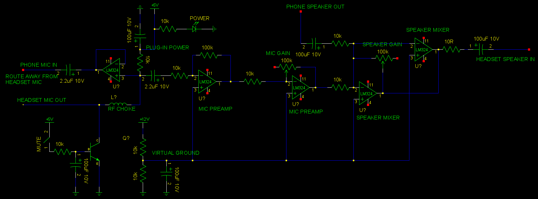
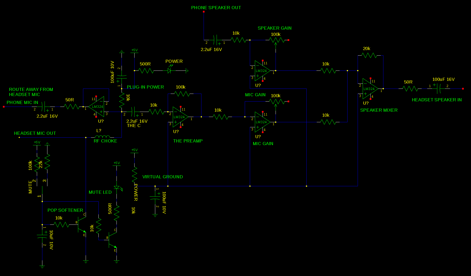
Then, there was the idea of using a confuser soundcard to mix the microphone with speakers for monitoring, but the microphone would have to be split & sent back to the phone.  To keep emissions from the phone out of the confuser soundcard, there would have to be an RF choke & voltage following amplifier.    It would need some kind of mute button which didn't make pops.  Android's mute button with non sensical screen blanking is useless.  There would be powered analog electronicals no matter what.

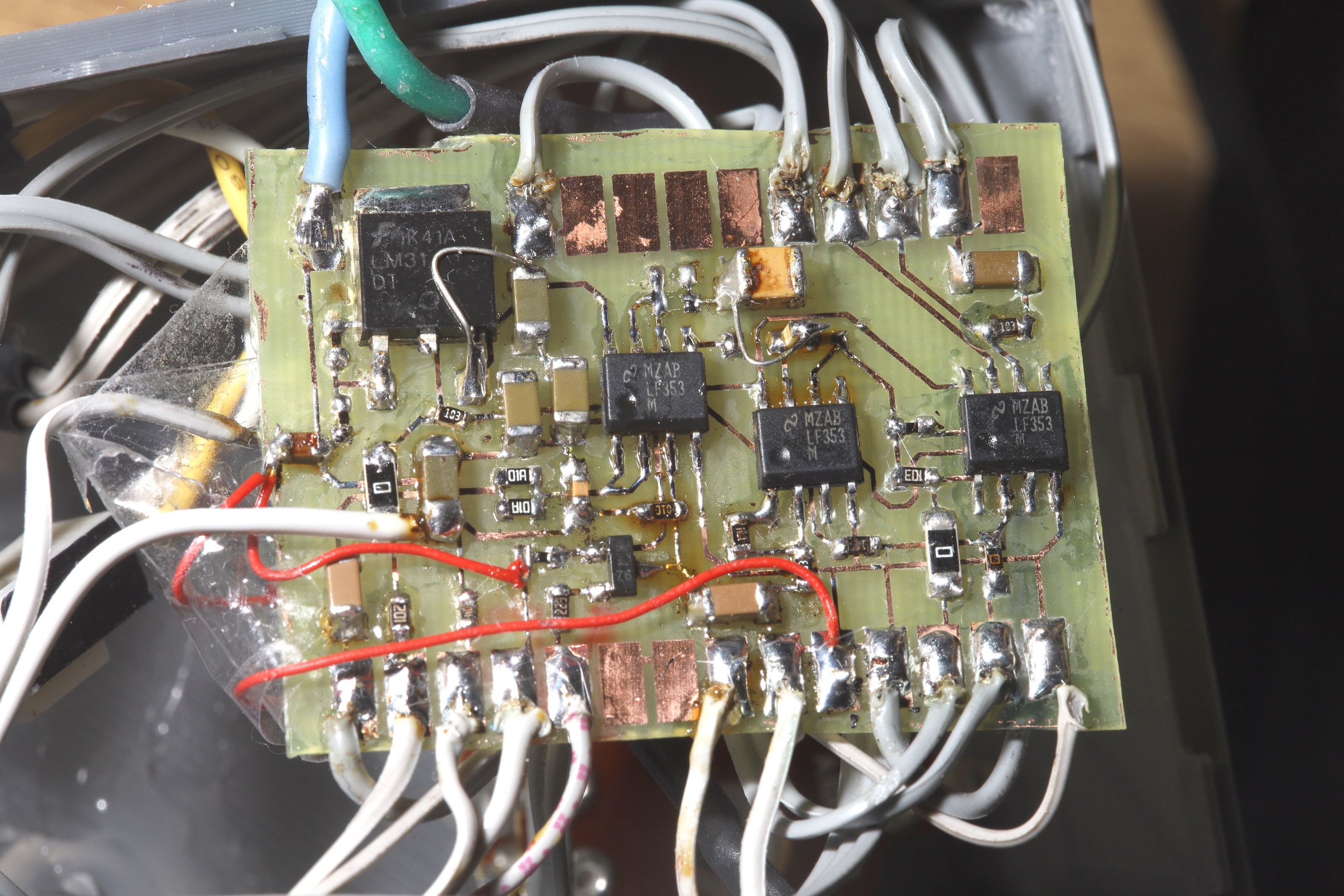
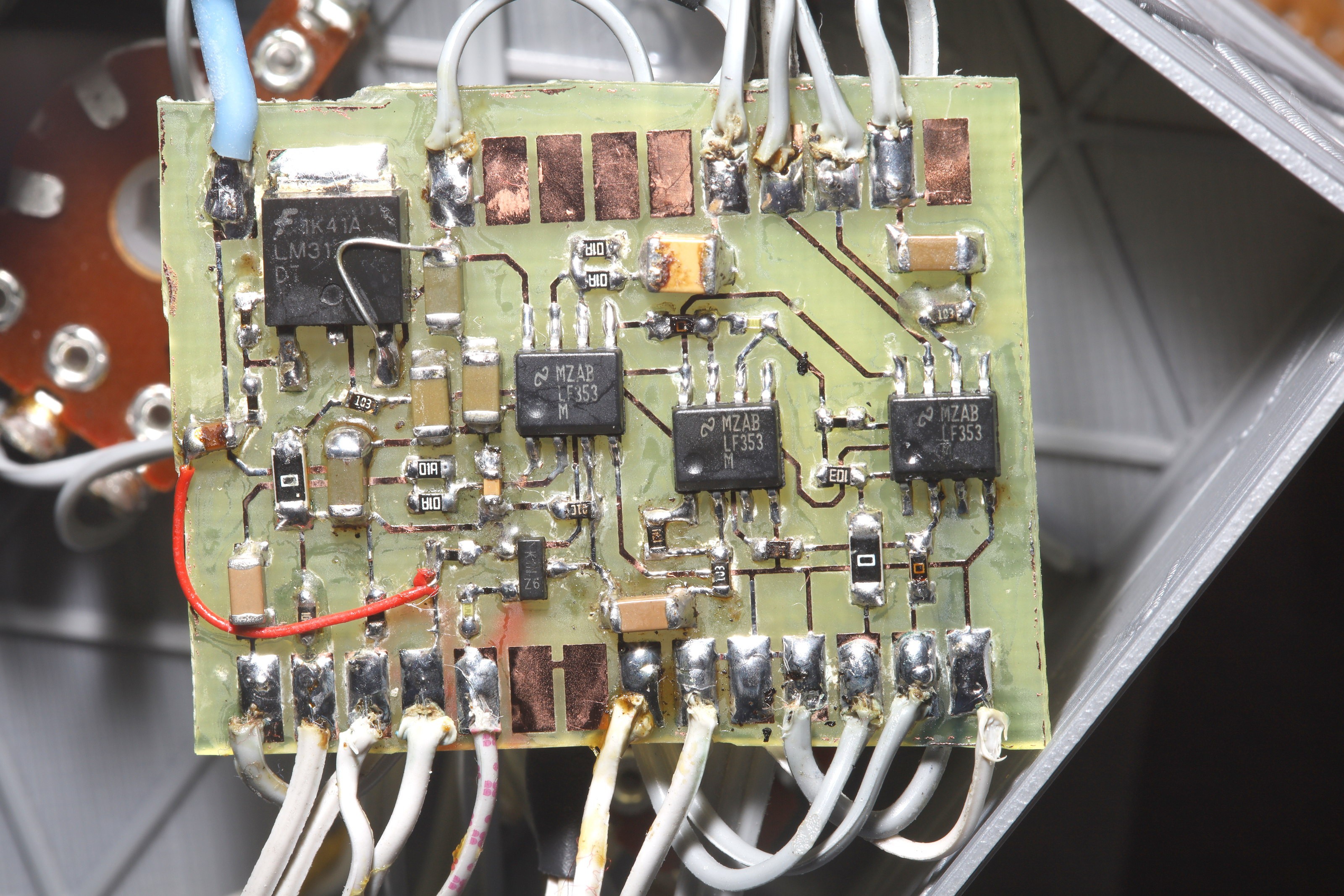
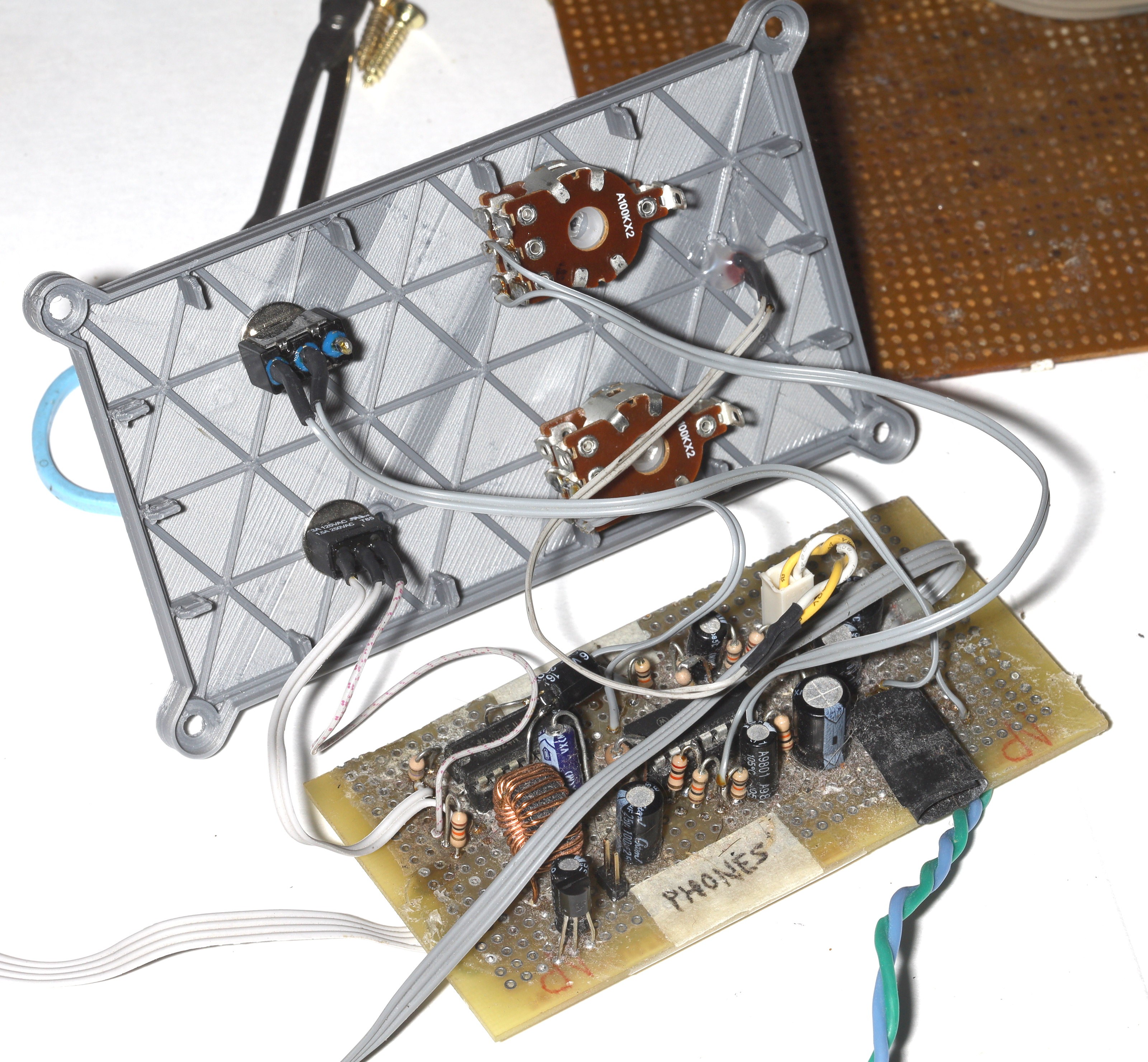
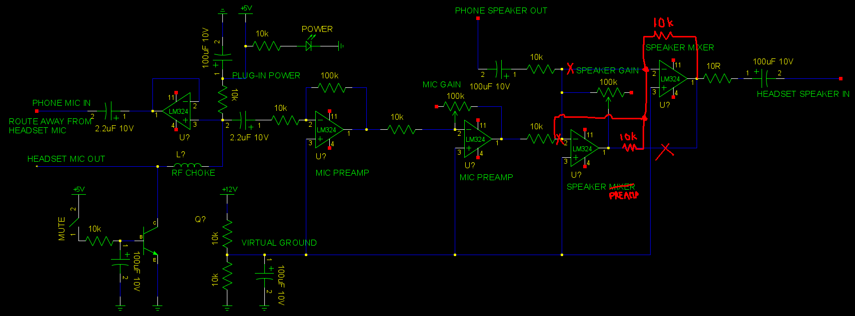
This was 1st solved in 2012 with an analog headset monitor.  It was a very large circuit board for what it did, using multiple LM324's to mix the microphone with the speaker output, power the speakers, & isolate the microphone from the phone.  The original also had a large inductor to shield the microphone amplifier from the phone's RF emissions.  

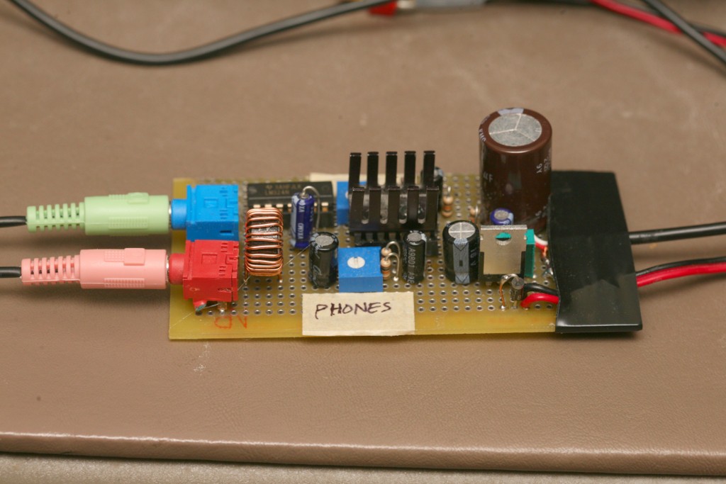
8 years later, it had grown into a quite complicated circuit.  The mane additions over the years were an LED to show when it was on & a simple transistor to mute the microphone by grounding it.  It also needed a resistor after the speaker mixer to prevent op-amp oscillation.

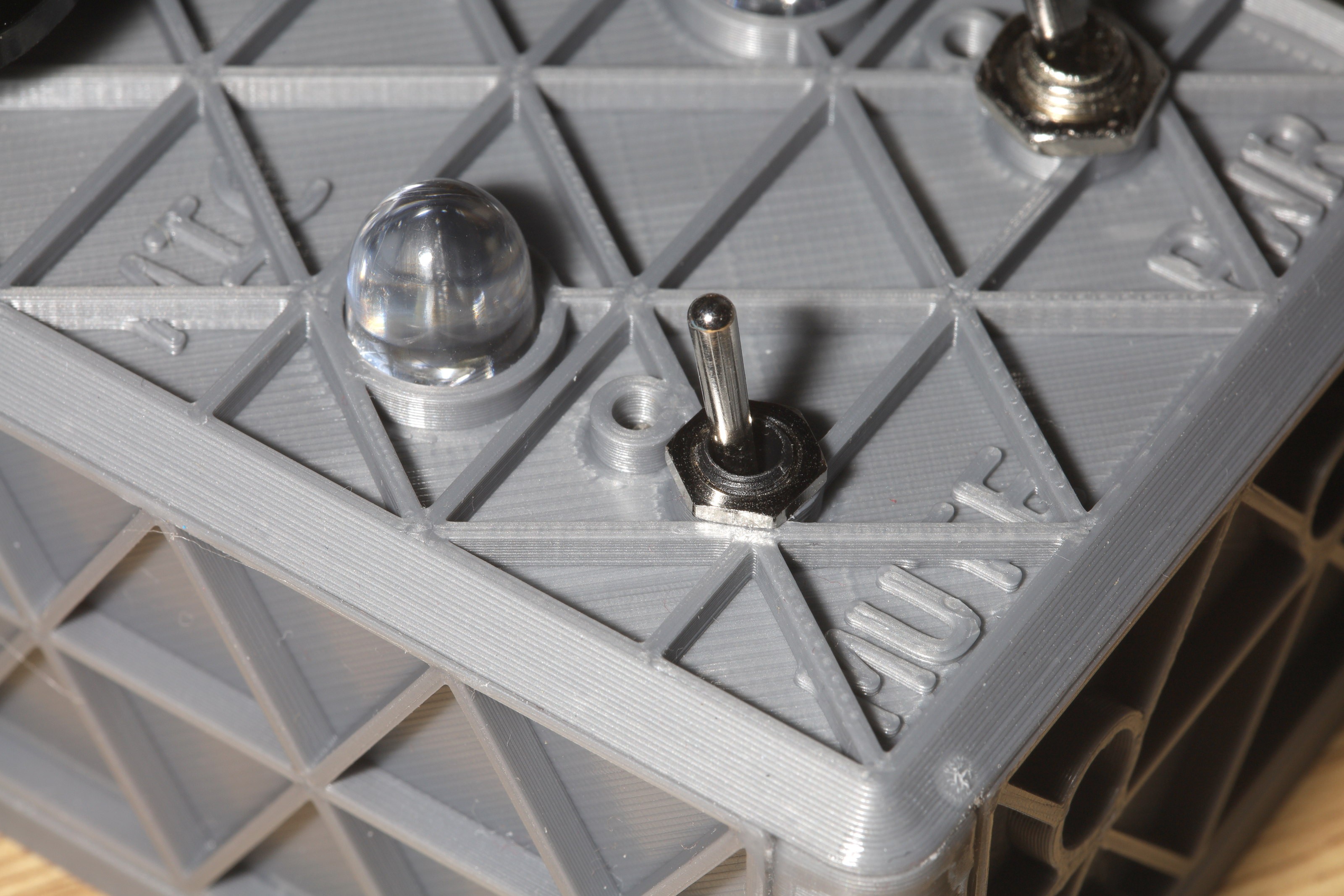
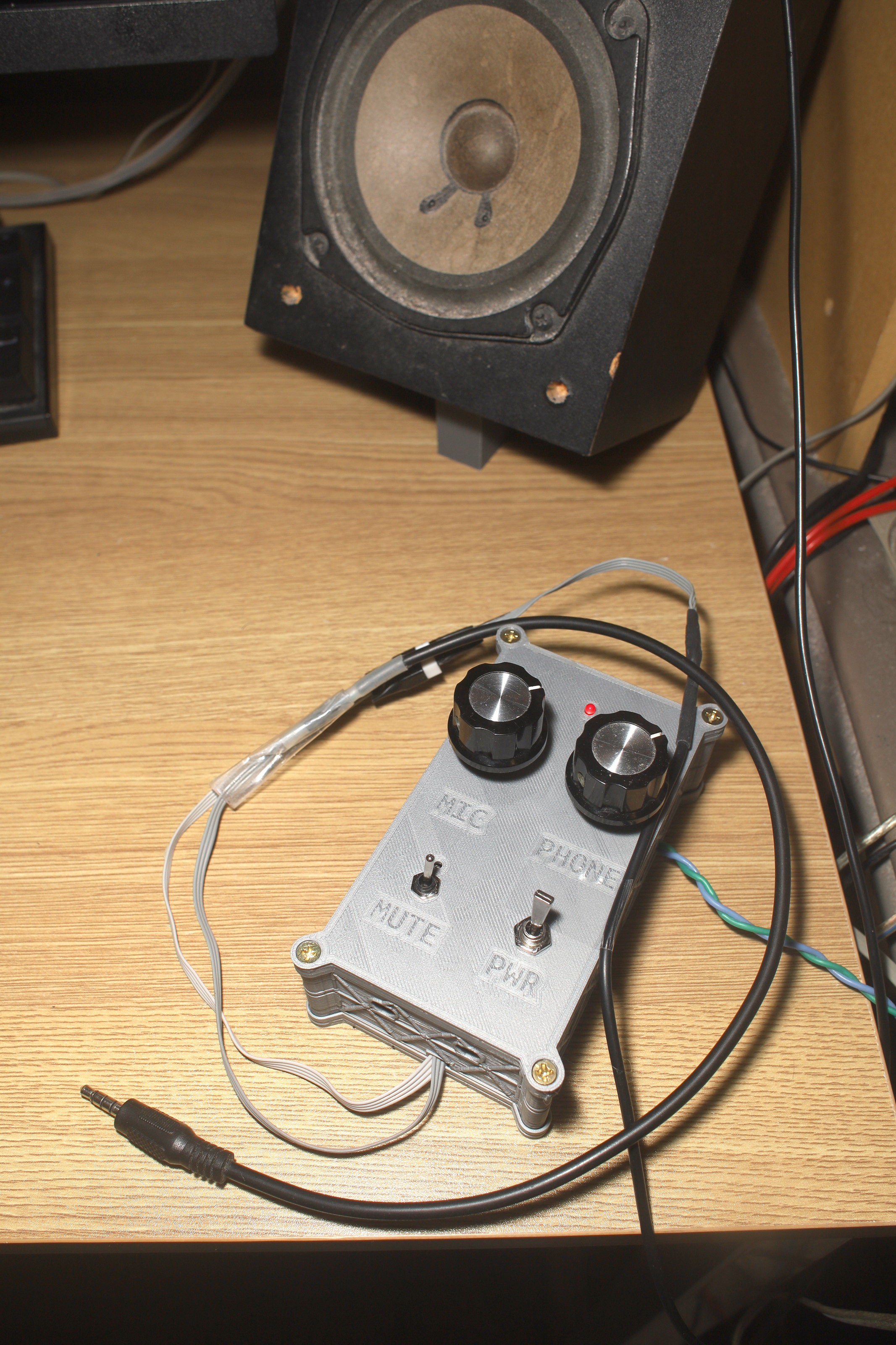
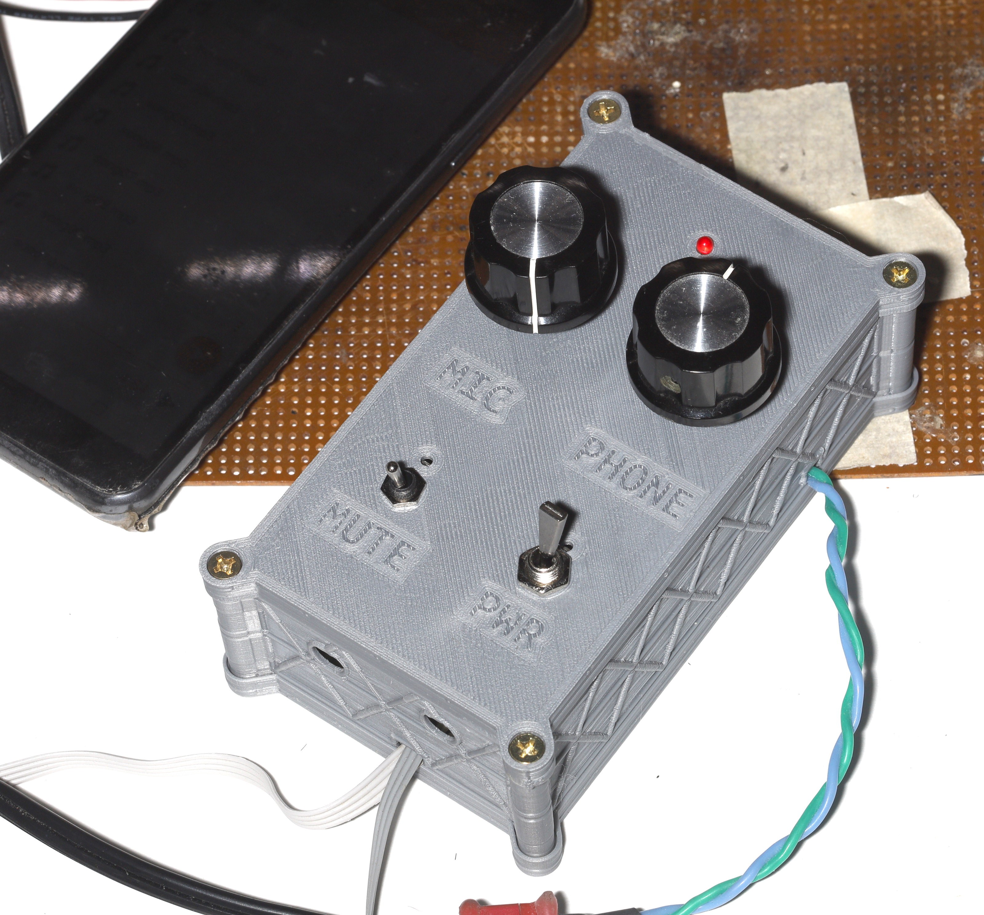
Because the Alphabet corporation doesn't allow us to have our phone screens on while making a call, it's very slow to toggle the software mute button. The lion kingdom finally added a mute switch to the headset mic out. 

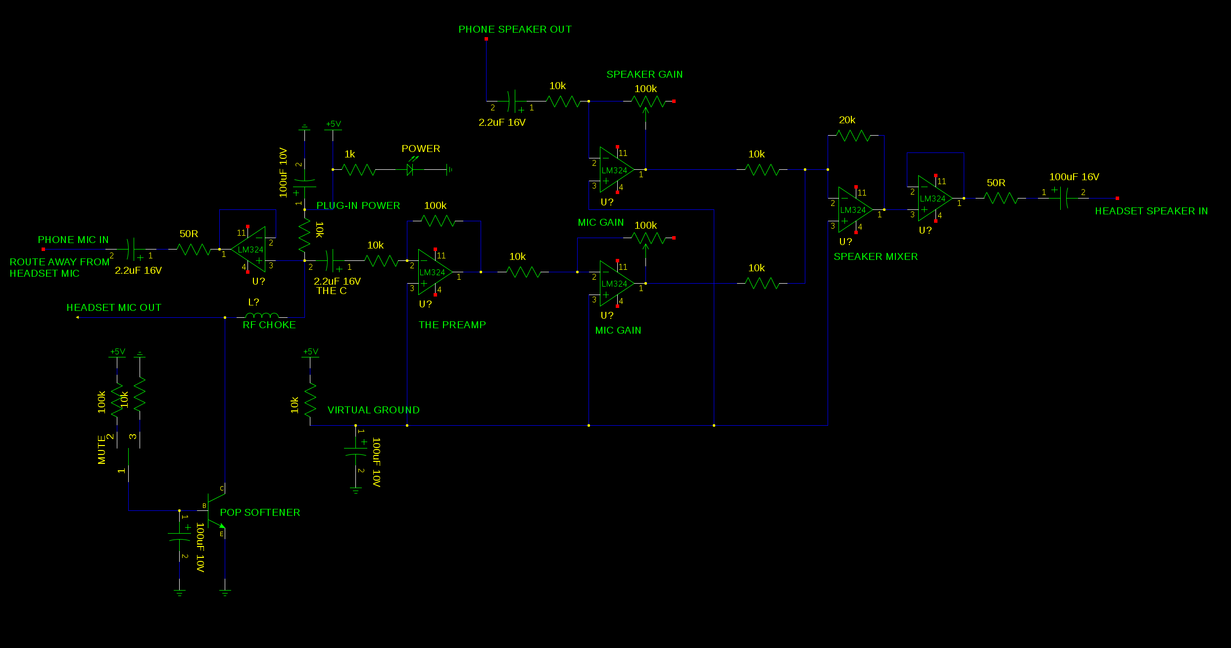
Using a switch to disconnect the microphone didn't work because RF just entered the floating wire.  Turning off the phantom power didn't work because the microphone still  detected sound without power.  Turning off the voltage follower didn't work because current still flowed through the op-amp without power.  Directly grounding the microphone made too much of a pop, but muted it. 

Only a transistor turned on by an RC circuit could ground it without too much of a pop.  There always must be a pop, since the microphone turns on at a threshold voltage instead of gradually getting louder.  Only an NPN transistor would work, since it has to pull the voltage to 0.

The mane problem is the speaker gets louder when the microphone is muted.  Not sure why this is.  

The original design regulated 12V down to 5V for phantom power.  Having 5V later proved useful for muting the microphone & powering an LED.

The original had 2 op-amps shorted to power both speakers in parallel.  It could have used 1 op-amp for each speaker, but it would have required separate pots for each speaker.  

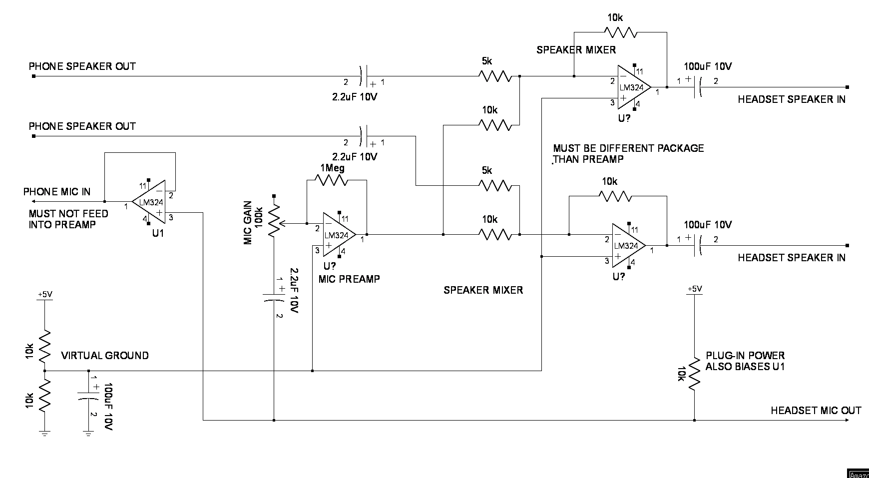
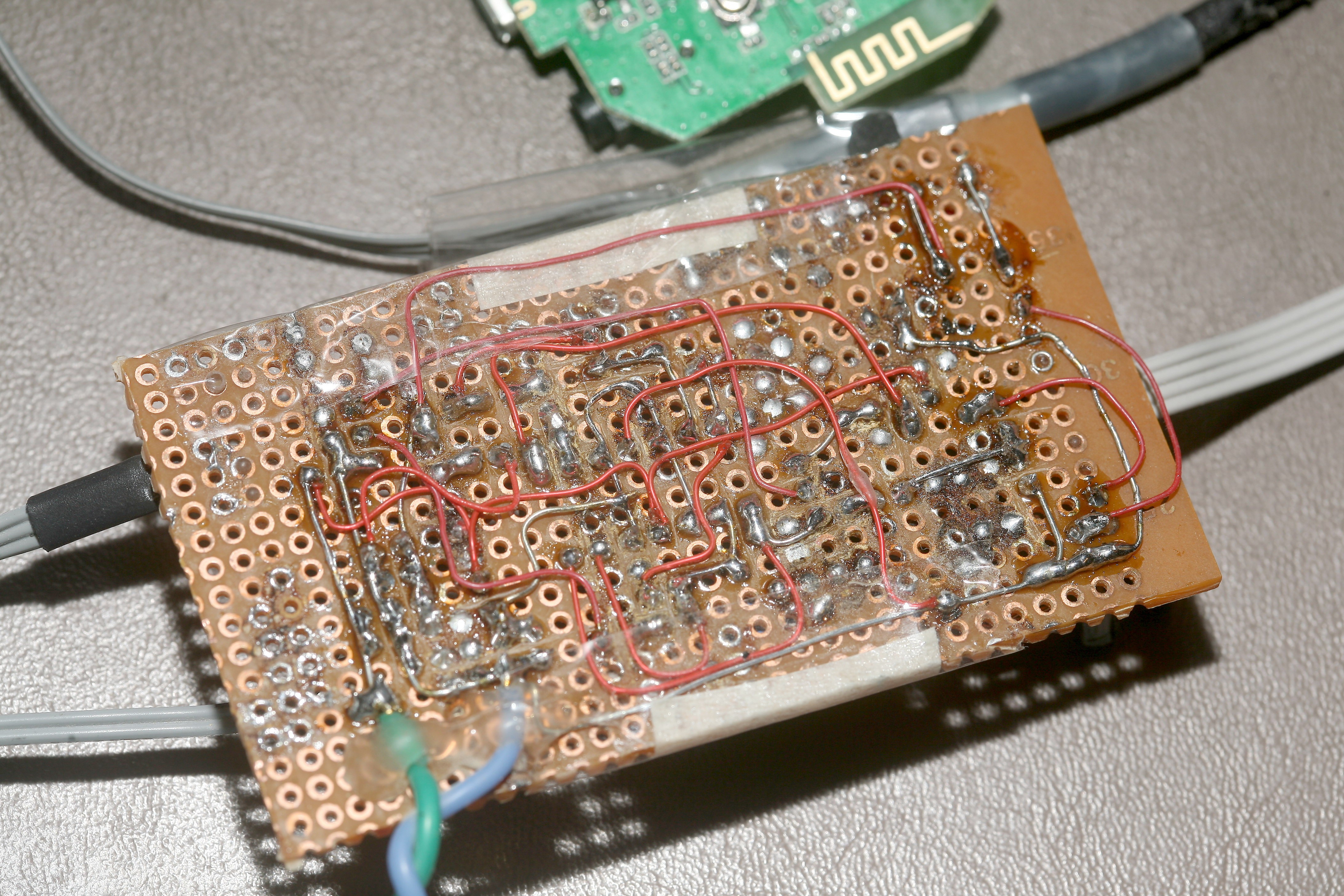
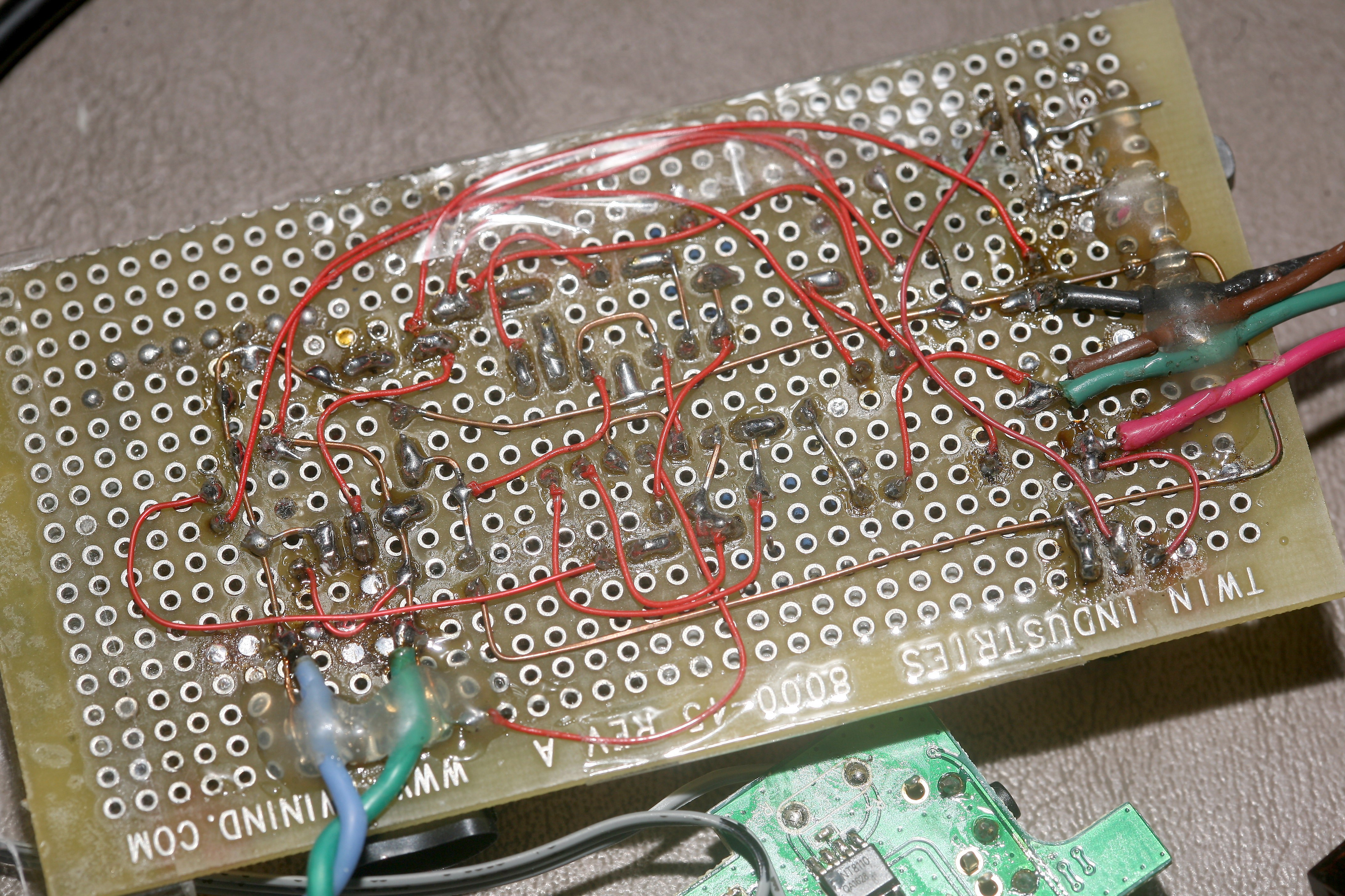
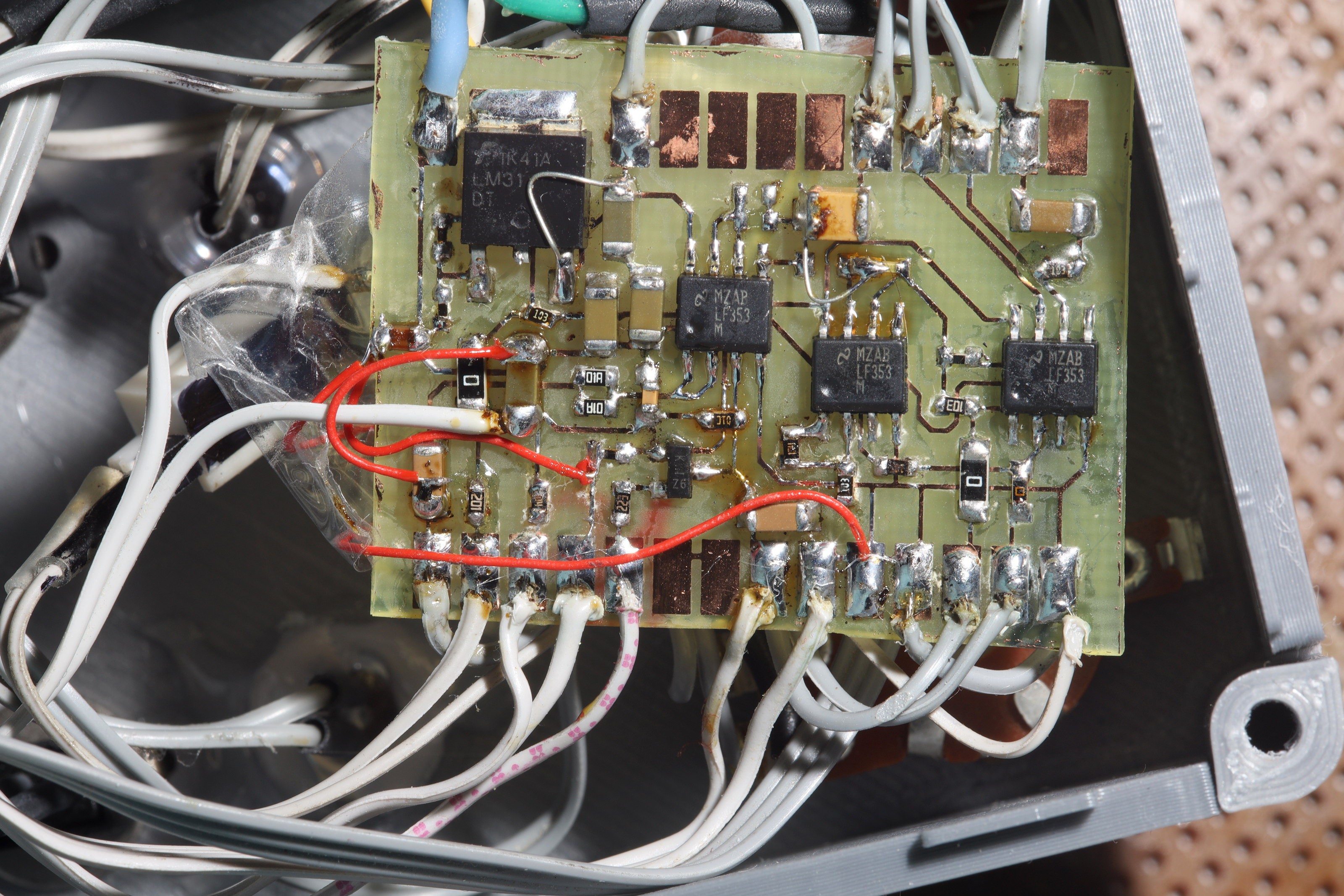
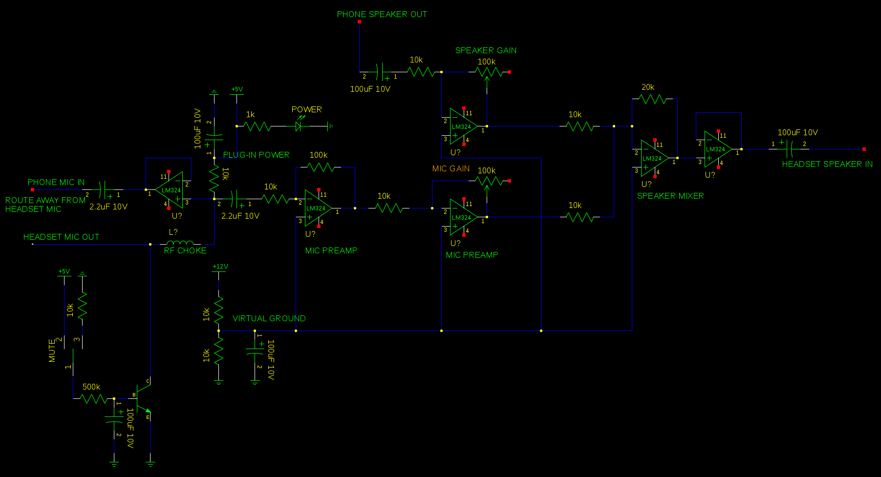
The original circuit was rebuilt twice, over the years, using surface mount & higher efficiency AD8604 op-amps.  The rebuilds left out the inductor & had stereo sound.  They had fixed gain for the speakers & mixed the same microphone signal into both speakers, after the preamp.

These redesigns proved fatally flawed.  The AD8604's needed a 10R on the speaker output to stop oscillating.  Newer phones, despite not using GSM, still produced interference which required the inductor.  The higher efficiency AD8604's had serious feedback & crosstalk problems the LM324 didn't have.  They might be intended for digital amplification rather than audio amplifiers.

The original design ganged 2 op amps to drive the speakers in mono. The new designs drove the speakers with 2 op amps in stereo.  The original design used cascaded 10x amplifiers for the mic preamp. The new designs used a single 100x amplifier for the preamp. As in the original design, a voltage...

Read more »

  • Android microphone detection

    lion mclionhead11/18/2021 at 18:44 0 comments

    So the big change between modern phones & the Lucky Goldstar phones lions used for 10 years is the goldstars detected the short circuit created by the ground ring while all the new phones detect a resistor between ground & microphone.  A 5k resistor allowed the modern phones to use a wired headphone, but the circuit has become quite complex for what it does.

    Sadly, new phones no longer allow tapping call audio to draw a VU meter.  They allow drawing a VU meter for voice over IP only.  

  • Death of wired headsets

    lion mclionhead10/20/2021 at 21:50 0 comments

    So the paddle switch for mute is very satisfying, but really does make a lot of noise in the audio because the mute is delayed.  The other problem is the 2 paddle switches interfere with the LEDs.  Thus began ideas to use quieter MHPS2283 switches.  The ideal switch would be without clicks but inaudible switches feel terrible, take a lot more space & are expensive. 

    Farstening an MHPS2283 switch to a panel is a bit harder than a paddle switch.  It needs to be supported from the opposite side.  All the lion kingdom's last order of MHPS2283 switches will have been accounted for.  

    It ended up easier to just handle the paddle switch with 2 fingers to make it silent.  The silent switches in broadcast studios are for speedy accessibility.

    Sadly, the lion kingdom's next phone came in & although it has a headphone jack, it doesn't support an external microphone.  It seems all new phones only support microphones over bluetooth, despite the headphone jack.  Moving the headset circuit to bluetooth has been problematic.  The microphone input has a lot of noise.

  • Speaker to microphone crosstalk

    lion mclionhead10/20/2021 at 04:08 0 comments

    The crosstalk of 10 years ago returned.  The mane cause was narrowed down to sharing the same package with the microphone follower & speaker follower.  Taking out the speaker follower ended most of the crosstalk.  The microphone follower proved essential to get enough microphone gain.  A small amount of crosstalk remaned when the phone volume was maximum.  Lowering the phone volume halfway got rid of it.  

    After taking out the microphone follower, taking out the phantom power, having the microphone pass directly to the phone, the same amount of crosstalk existed.  Changing the speaker gain on the circuit had no effect.  Only lowering the phone volume ever got rid of it.  The cause was believed to be in the phone itself.  There is enough gain in the headset circuit to make up for a lower phone volume.  

    The amount of rework & flux is quite a mess.

  • Enclosure #3

    lion mclionhead10/18/2021 at 20:29 0 comments

    This enclosure got 10mm longer to make room for the pots & RCA connectors.

    It occurred to the lion kingdom, after sending enclosure #3 to the printer, that the reason commercial products are all smooth on the outside instead of faceted like lion designs is so they can be cleaned.  Cleaning the faceted designs would entail a cue tip & forget about getting any food out.

    So the F-35 nozzle after 1 year has a coating of dust which can't be easily cleaned, but it could be more easily cleaned than the headphone monitor because the grid is lower.  Faceted exteriors are more useful when the part can be washed.

    A better enclosure would be printed in 2 pieces with all the grids on the inside.  Isogrids have only been rigid on 1 axis, making orthogrids more useful on planes & isogrids more useful on cylinders.  On a single piece bathtub, orthogrids are hard to print vertically.  An isogrid would still be preferred on vertical walls, since it doesn't need horizontal lines.

    The lion kingdom will wait for the headphone monitor to get dusty, then print a 2 piece bathtub instead of trying to clean it.

    Cable routing is a hard problem & the lion kingdom ran out of time.  The latest plan is to make a magnetic hook for the desk.

  • Enclosure 2

    lion mclionhead10/16/2021 at 21:15 0 comments

    The 1st artistic enclosure was designed over 3 days.  

    Even the underside is artistic.

    The new set of jumbo LEDs gave it a true retro look.  The mute LED seems essential, now that it's installed.  There's a perceptible brightness delay as the mute fades on, even though mute still pops because the electret condenser is either on or off. There is no delay as the mute fades off.  Some more resistor tweeking would be required to perfect the fade delay, but normally you want the mute to turn off as fast as possible without popping while turning on can be slow.

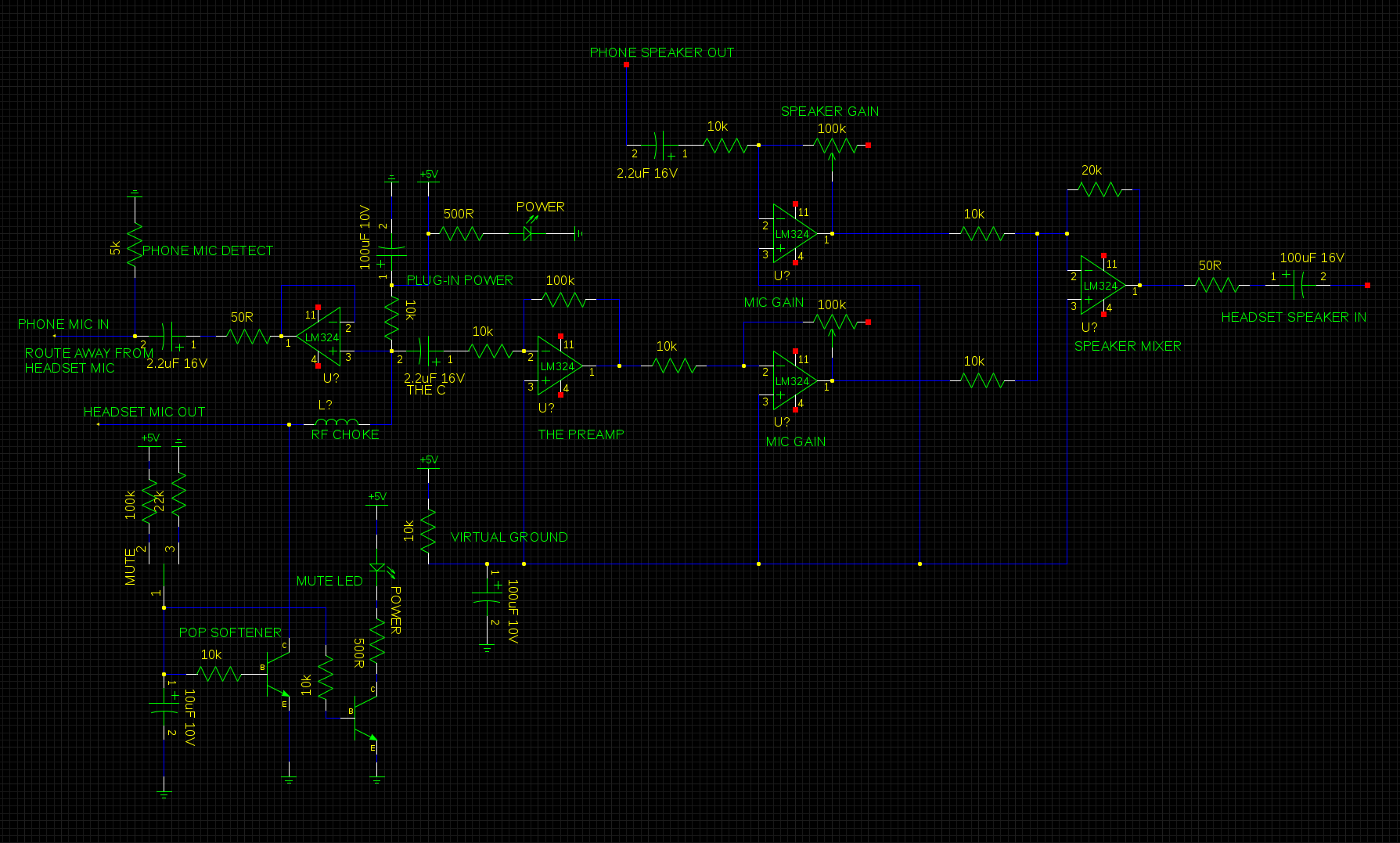
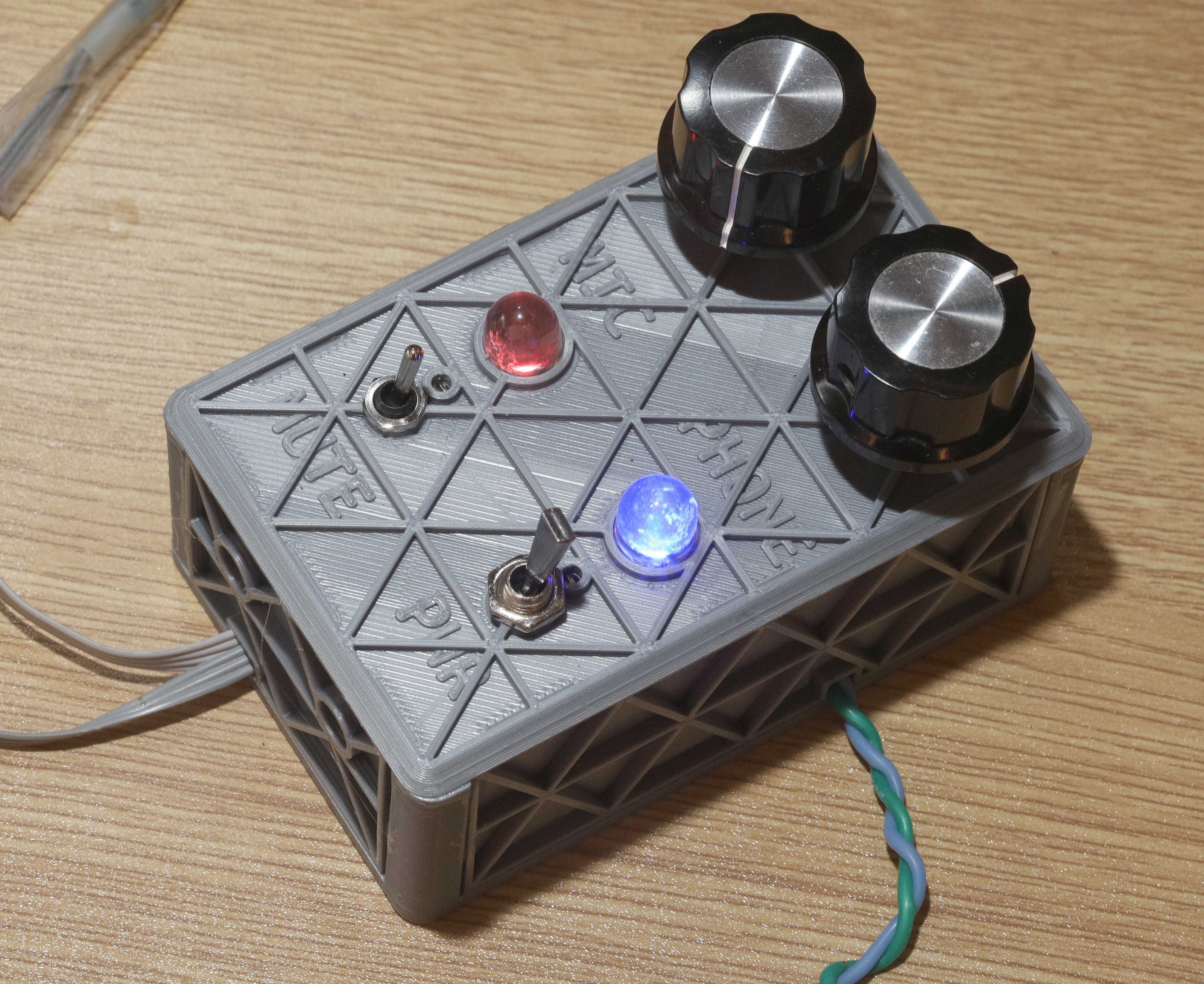
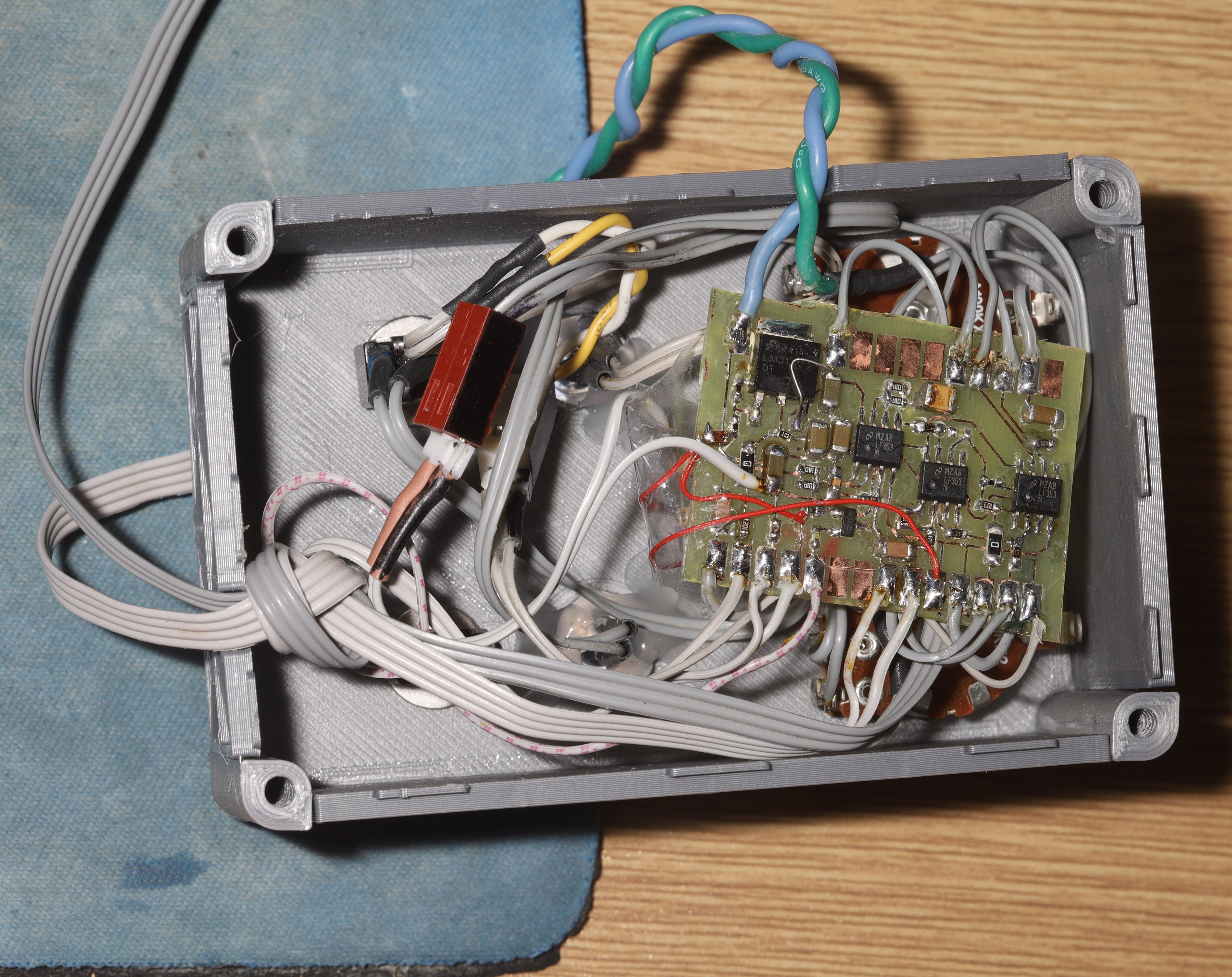
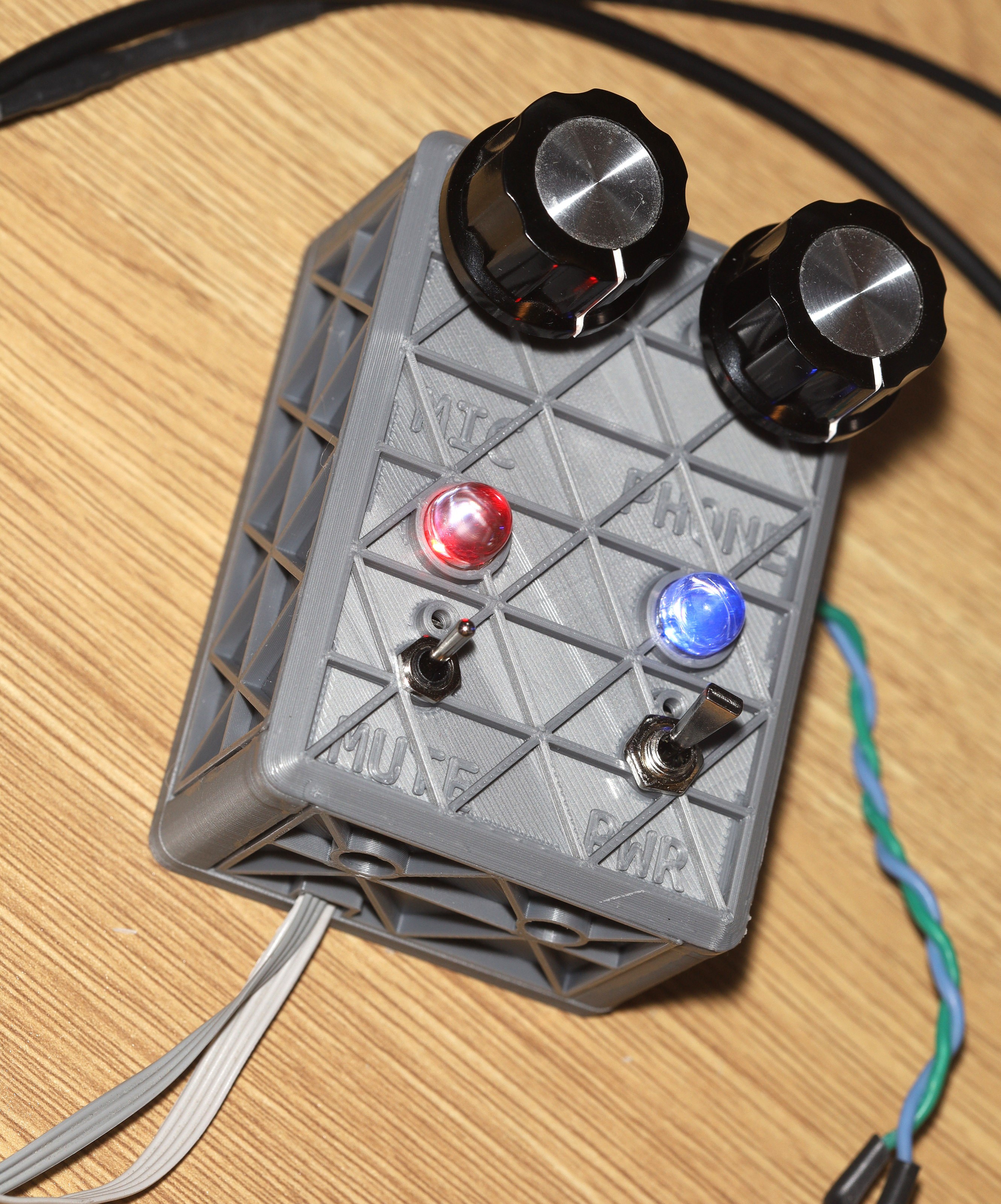
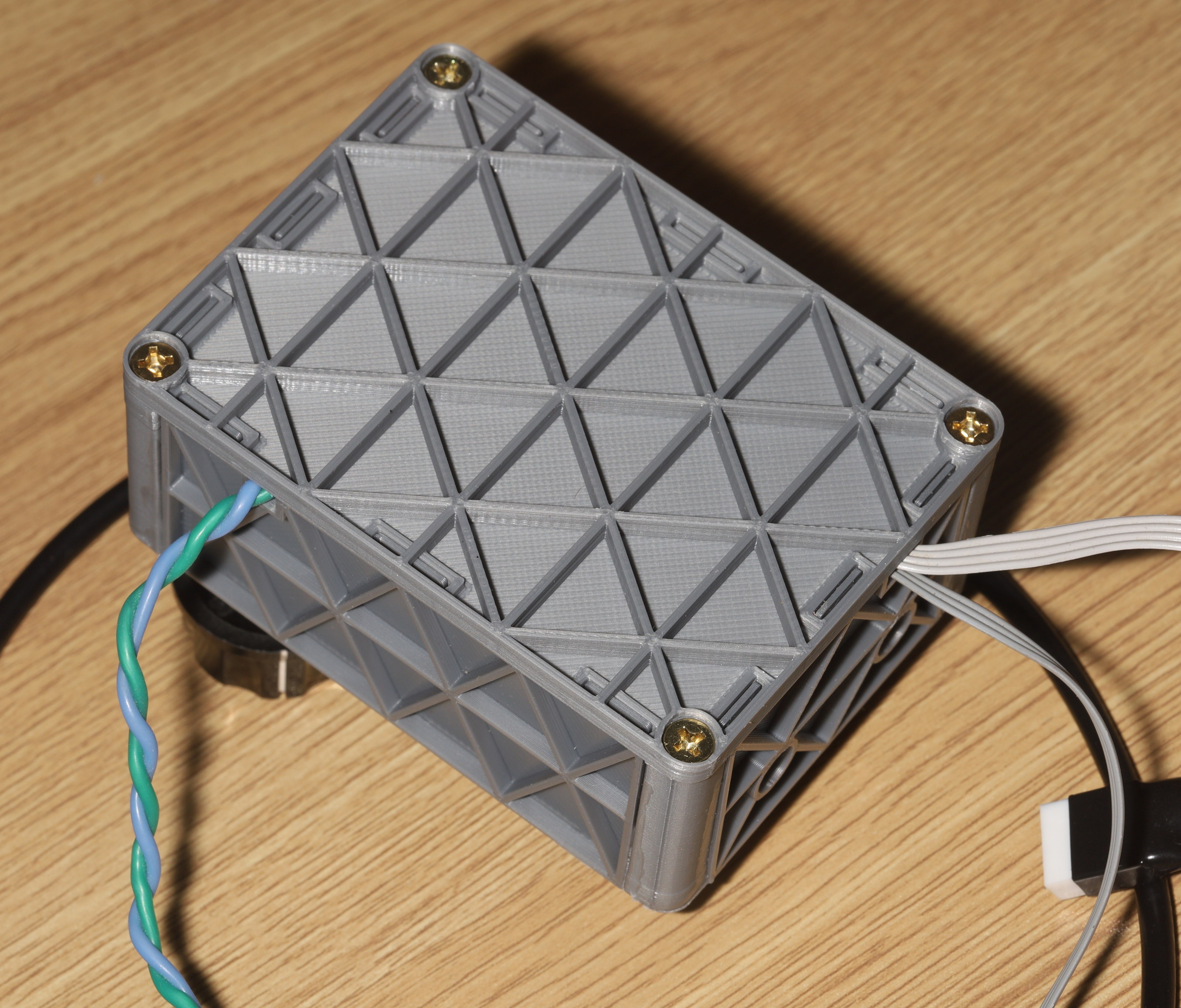
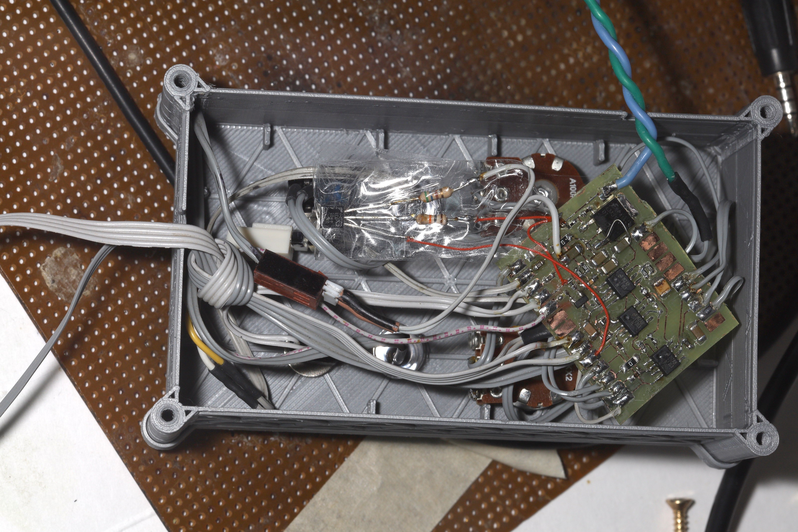
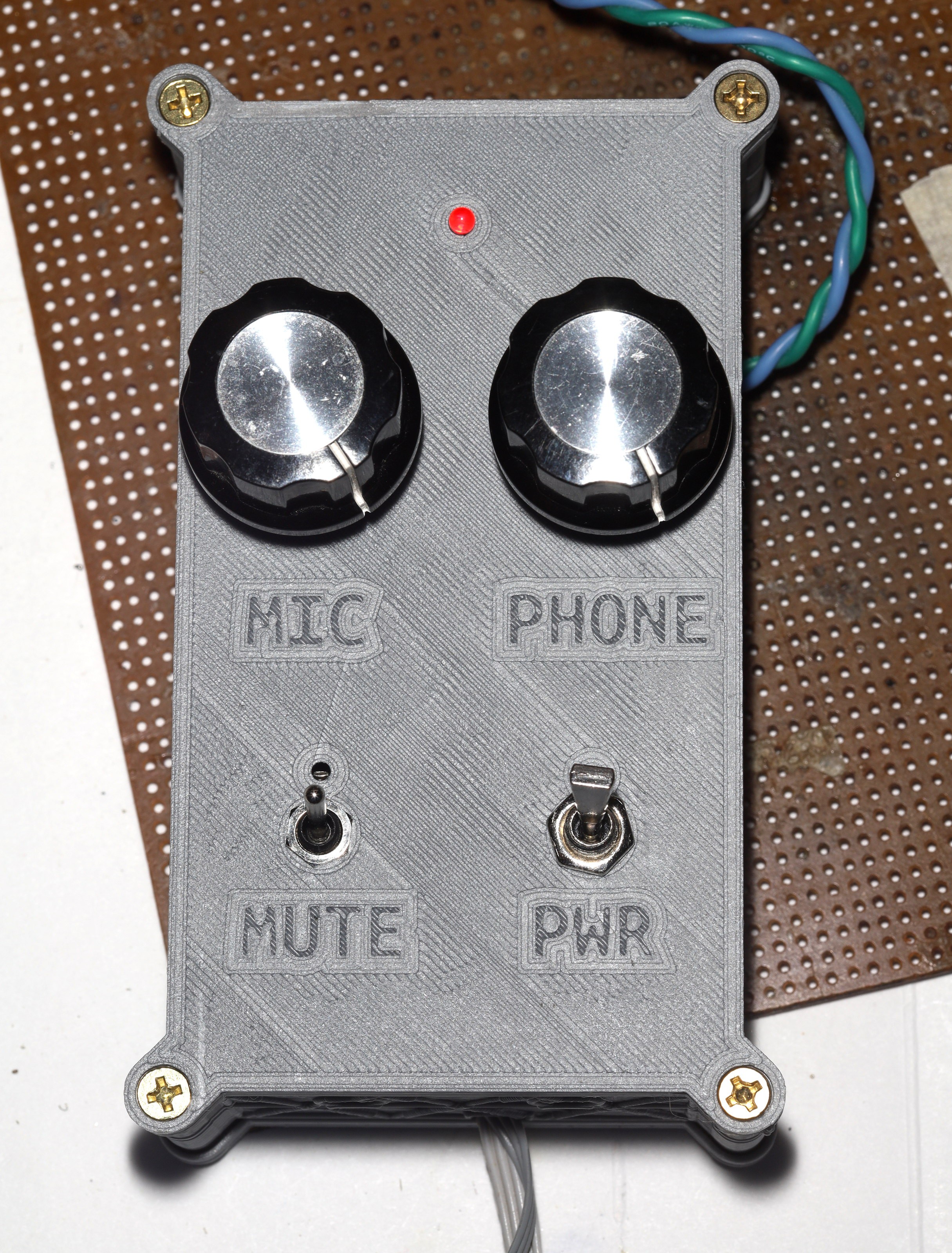
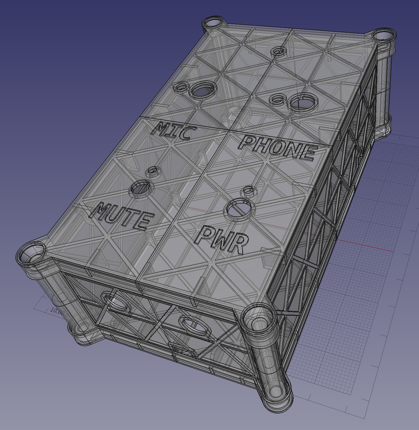
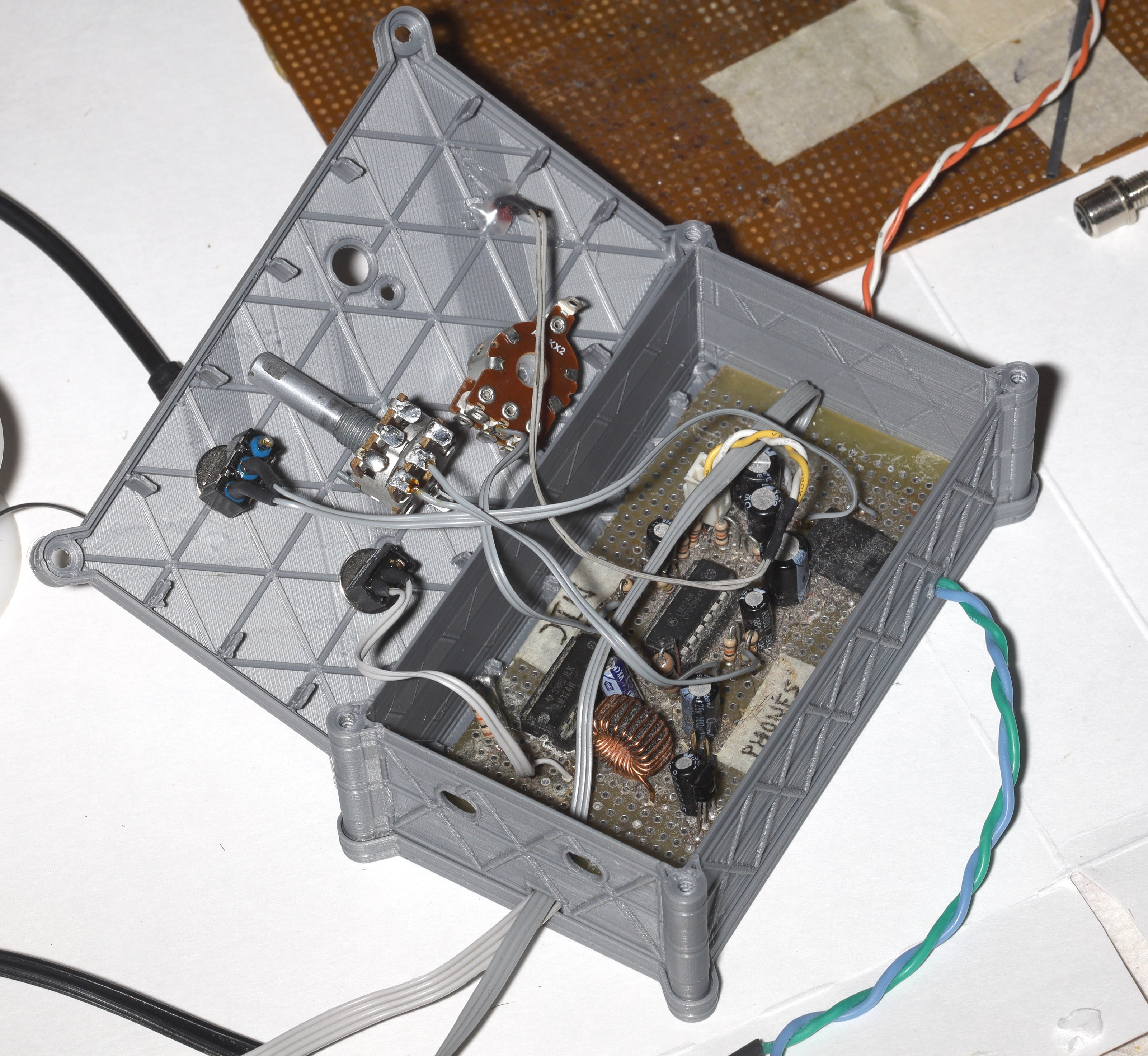
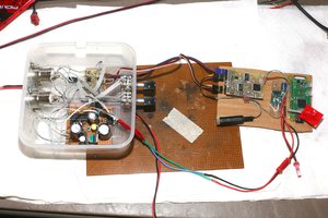
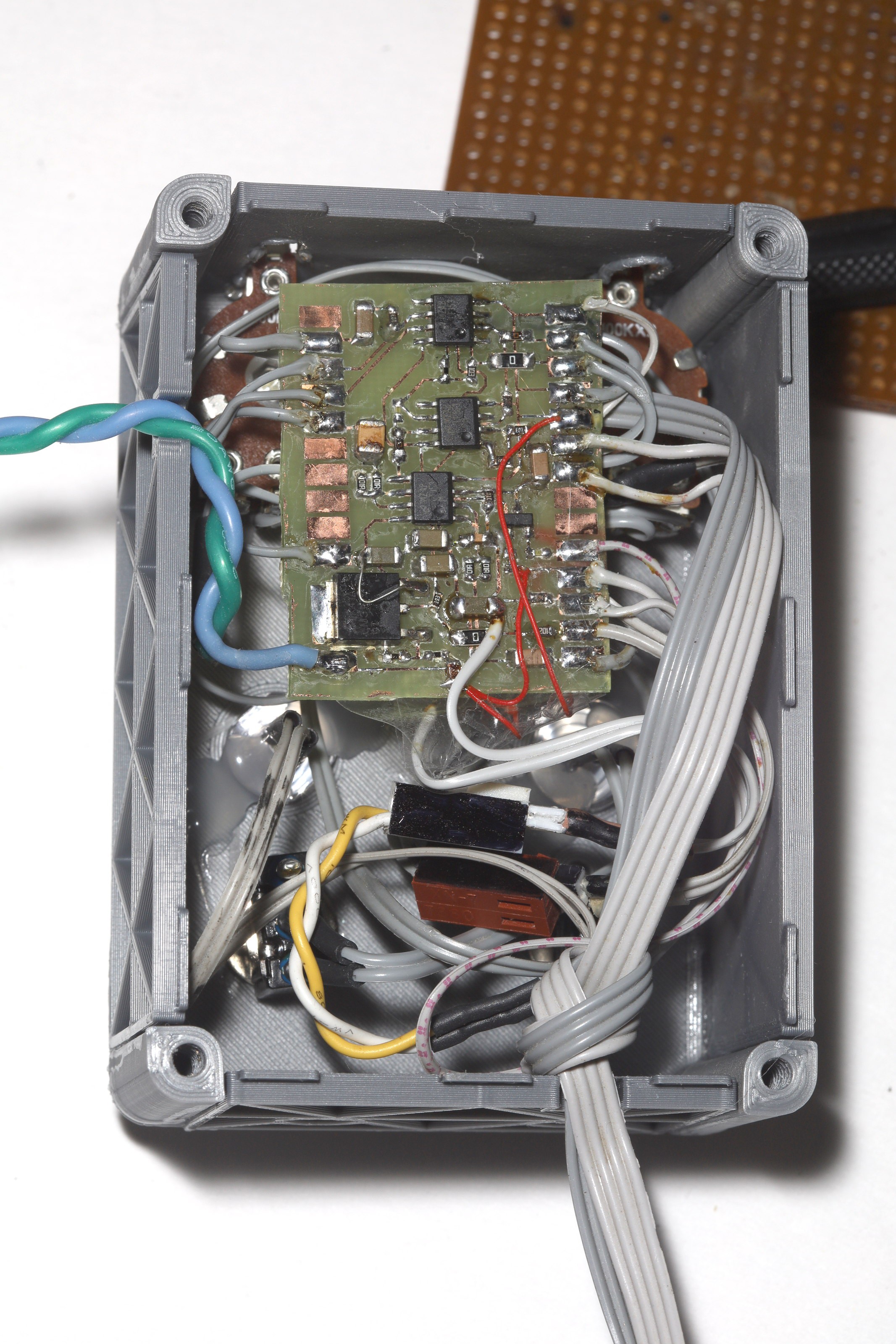
    The enclosure height is just enough to fit all the wires in without kinking.  A 100k turns the mute on & a 10k turns the mute off, hence why turning off is faster.


    There are still problems.  The pots don't fit.  There is a minimum spacing between pots & switches to avoid bumping into them, so the enclosure would have to get bigger.

    The top panel needs to be .6mm thinner.  Side panel still needs a hook for cable management.

    The switches are too noisy to ever be used in a radio environment, but they would never be toggled around a live microphone.  The clicks are what sells.

    The corners ended up small enough to not need any artwork, but they don't interlock at all.  The mane challenge is interlocking panels which are printed horizontally with corners which are printed vertically.  They need protruding tabs on the bottom & recessed notches on top to interlock with the panels.

    The inside got a lot more packed with a BJT for the mute LED.

  • 1st SMD success

    lion mclionhead10/16/2021 at 08:11 0 comments

    After 2 hard days of dead ends, bodges, & blown traces, the problem was solved.  The always dependable LM317 was creating noise in the muted state.  The LM317 was always considered a very quiet voltage regulator compared to the LM7805, reliably powering MEMS sensors & audio preamps for years.  This was the 1st time it proved too noisy & there was nothing in the probing to reveal it.  It was just a matter of eliminating every other change since the through hole board.

    A 10k 100uF RC filter got the noise back to what it was on the through hole circuit, making this the 1st SMD iteration which actually worked.  The mane problem in previous SMD boards was slightly tweeking the connector causing an overload feedback oscillation.  That hasn't happened with board #3 so far & the noise was the only other issue. 

    The mane question has been adding an LED for mute mode, but the only way to know if the LED indicates muted or on is to listen on the phones, so it's quite useless for anything but bling.  Helas, this board is already nothing but bling.  The giant knobs & switches are completely superfluous & it would be better to have the power LED next to the power switch.

    It would be a matter of whacking in a 2nd mute transistor to turn on the LED when muted.  It would be a lot harder to turn off the LED when muted.  Back when we commuted to offices with land lines, the old polycom phones lit a red LED when they were muted even though no-one knew what it meant in practice.

    Also, upgrading the LEDs to giant size would be another superfluous bling on top of the bling.

  • Rework

    lion mclionhead10/12/2021 at 05:42 0 comments

    So the next rework gave it the previously described changes + a 2:1 makeup gain on the summing amplifier to recover some of the gain lost by not cascading the microphone preamp.  There's also a voltage follower to try to aid powering the phones.  The mute switch got some new resistors to try to soften the pops.

    1 of the pots was rediscovered to be defective after the 1st discovery, 10 years ago.  

    There's now a long delay on startup where the microphone doesn't mute.  There should be another resistor limiting the base current.

    There's not much gain before distortion, but the independent gain is a lot easier than cascaded gain.  Not sure if it's trouble powering the headphones or the limit of the LM324.  

    A better op-amp would be the next step.  The next circuit would have to be surface mount.  While through hole is visually appealing, it takes too much room.  The entire surface mount circuit would fit on the underside of the control panel.  

    It needs some holes on the side & a zip tie to manage the cables.

    Despite its tactile appeal, the audio quality & real estate is a disaster compared to what a soundblaster 16 could do 30 years ago.  The microphone & speaker could be fed into any modern sound card, mixed in 16 bit PCM, & sent to any speakers with a few lines of software.  There might be a single analog circuit to split the microphone between the phone & confuser.  The confuser only has a single analog output with 2 channels.  Maybe an adapter could split the output into a mono headphone & a mono microphone output.

  • Enclosure

    lion mclionhead10/11/2021 at 05:33 0 comments


    After 10 years, the headset amplifier became a daily necessity so a long awaited enclosure was fabricated.  The enclosure was the 1st attempt at large scale thin walled printing, .5mm walls to be exact.  It didn't look very good, but it was cheap for its size.  .5mm seems sufficient, as long as their are reinforcing ribs.

    4 hours of soldering yielded 2 pots & 2 switches.  It takes 30 minutes to solder a single component.  There is a place to have a line out, but it would involve 1 hour to solder 2 RCA connectors & a line input on the amplifier is a long way off.  

    The headset amplifier has made some progress but has a long way to go.  The phone volume has always really been a master volume.  For some reason, the phone gain was put into the output of a summing amplifier for the microphone & phone.  It might have been assumed that the phone would always be loud enough & lions wanted a master volume.  Experience showed the phone isn't loud enough & it's a pain to adjust both the microphone & master to get the right level for either input.

    A few more hours of soldering should give independent volume controls with no master volume.  

    The pots are 2 channels even though only 1 channel is used.  They are the only 100k pots in the apartment & they were bought back when it just involved running down to a Radio Shack.  Getting a 100k pot today would involve a 2 week delay & shipping costs.

    The debate continues of whether it's worth having a physical amplifier or using the confuser's sound card for conference calls.  The physical amplifier can be used for any call on a phone & any call on a confuser.  The confuser sound card would only be useful for those calls.  The confuser really needs presets for conference calls & videos.

  • Logitech H111

    lion mclionhead12/07/2017 at 22:58 0 comments


    Conversion of the logitech H111 into something more useful.

View all 9 project logs

Enjoy this project?

Share

Discussions

dearuserhron wrote 10/12/2021 at 20:43 point

Useful. Hardware monitoring without lag. Like it.

Schematics are very nice, I can reuse it at home to make intercom between rooms.

  Are you sure? yes | no

Similar Projects

Does this project spark your interest?

Become a member to follow this project and never miss any updates