 8bithalfadder
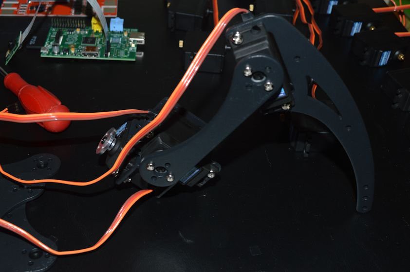
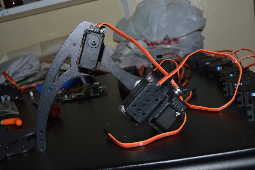
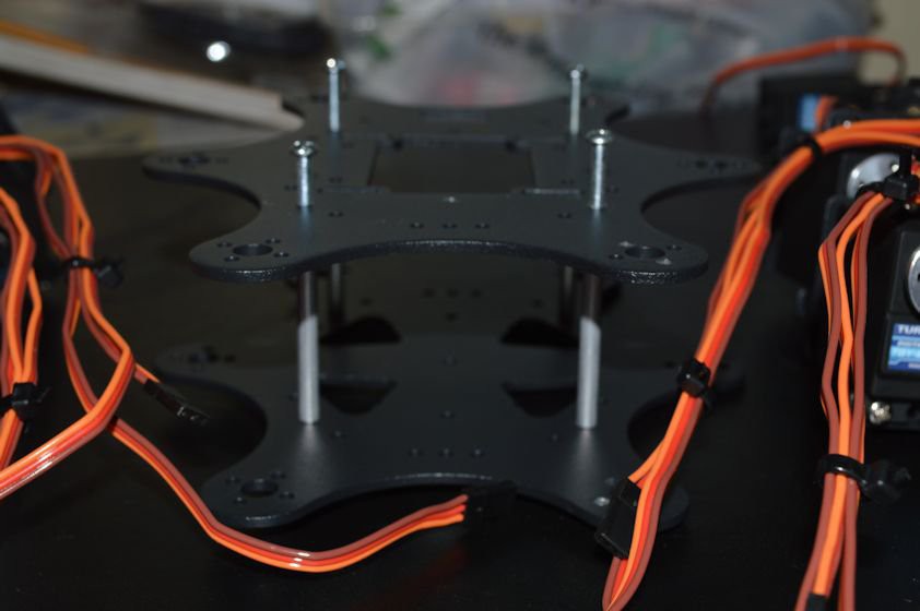
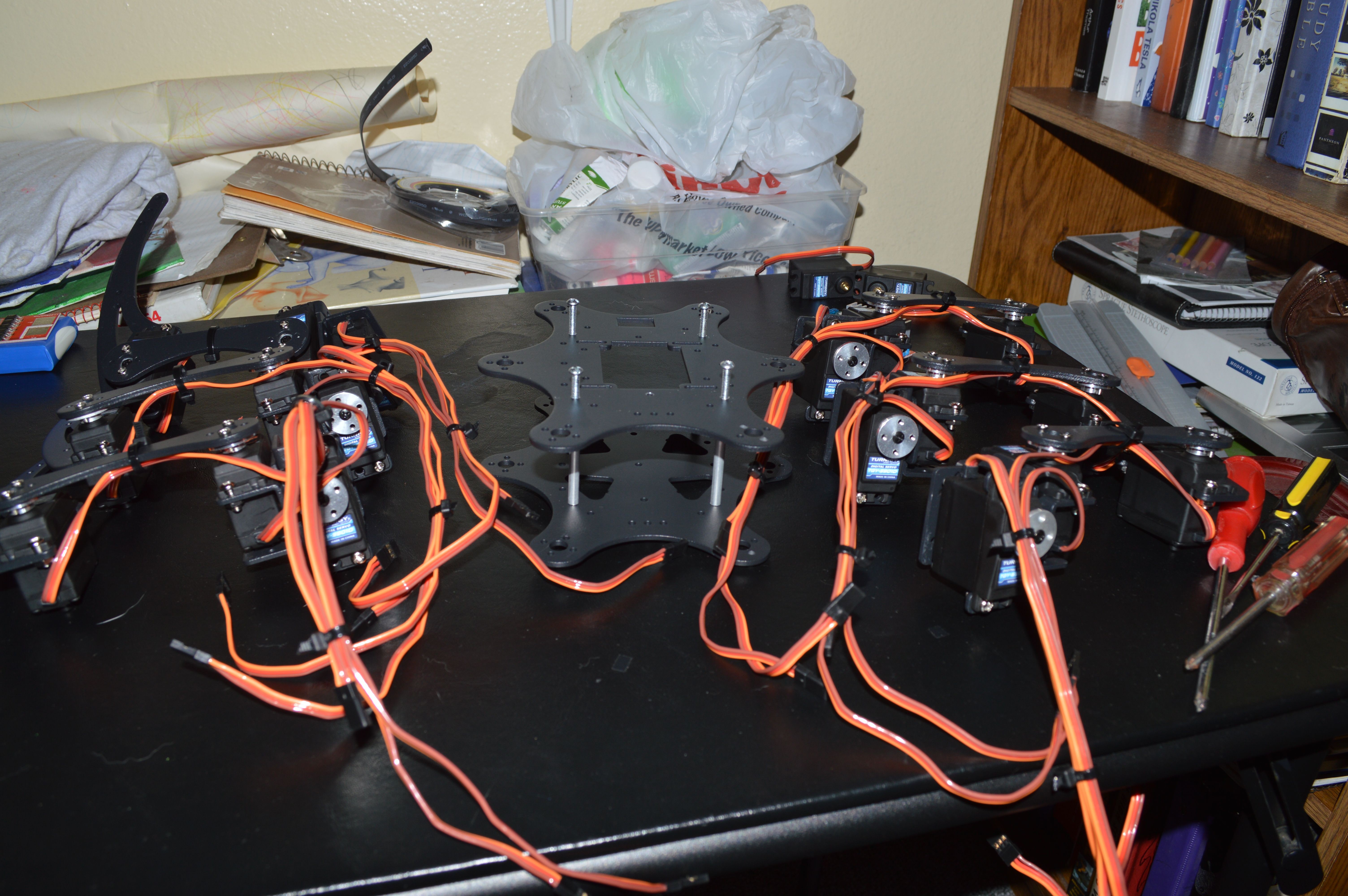
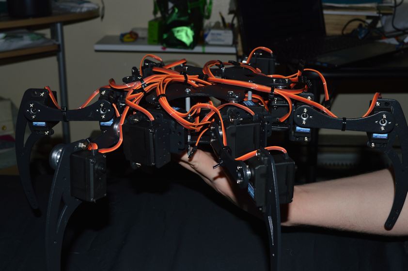
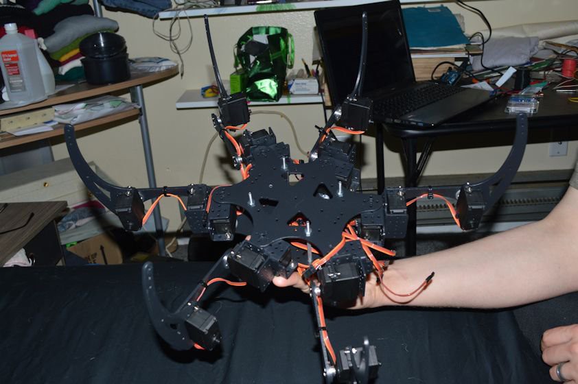
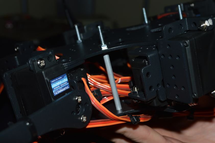
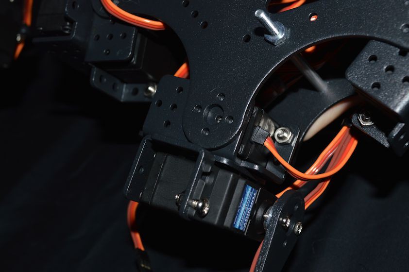
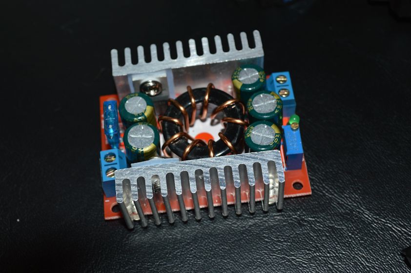
The general idea is to use the PI and camera to perform the inverse kinematic equations and to perform obstacle avoidance, this information is passed onto the servotor32 board to set the servo positions according to the IK equations. Everything will be powered from the 5000mAh RC battery which I'm installing a protection circuit onto to prevent overdischarge. The 7.4V from the battery is stepped down to 5V from the adjustable switching power regulator.
0%
0%
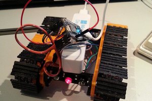
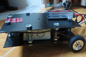
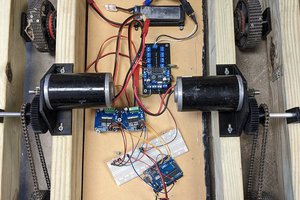
Hexapod
Building a hexapod for under $500 from cheap parts.
Become a Hackaday.io member
Already have an account? Log in.
Just one more thing
To make the experience fit your profile, pick a username and tell us what interests you.
Pick an awesome username
hackaday.io/
Your profile's URL: hackaday.io/username. Max 25 alphanumeric characters.
Pick a few interests
Projects that share your interests
People that share your interests


 David
David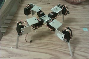
 morgan
i am also building a hexapod, and noted the servos you used. it must be coincidence, but i just happen to be using the same ones. have you ever had them "freeze" up on you, where they wouldn't move? that happened to one of mine, i took it apart and everything but couldn't find anything wrong, and before i order more, was wondering if this was normal?