This is my first article on this website. So the details are probably all over the place, and my english isn't exatcly godlike. But let me try to explain a few things:
Charging:
Is done via a constant voltage source on the solar panel side of things. I put a diode in series with the battery's so that nothing can flow back in the buck converter. The current here is around 1 ampere so there is no way of charging the battery's to quickly. Thats the first part of charging the thing.
The second part is on the right but first let me start with a little bit of data:
Red sockets: 15V AC/DC -- 60V DC MAX / 42V AC MAX
Black sockets: 7V AC/DC -- 20V DC MAX / 14V AC MAX
Let me start with the Red Socket part.
The power goes through a FULL BRIDGE RECTUMFRIER after that to a stepdown converter with a CC and CV source.
The Black socket part also starts with a rectifier, and after that goes through two boost converter's to step the voltage up to around 20V, so that the CC/CV buck converter can charge the battery.
Discharging:
The maxiumum current that i was still comfortable to supply where 50A. These currents are rather sketchy fused with to 25A fuses in parallel. I can discharge to around 10,6V without damaging the battery's.
Both the Red and Black sockets work independently.
After the main fuses already comes the relay, wich in turn switches the main fuse box.
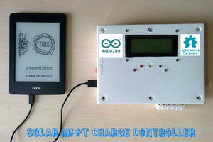
 Open Green Energy
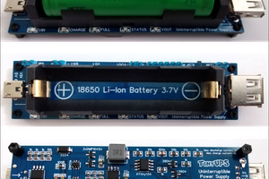
 Stefan Wagner
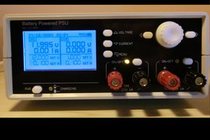
 Manuel Tosone
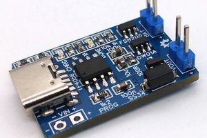
Yes, just a cheesy reference to AvE and Electro Boom.