0%
0%
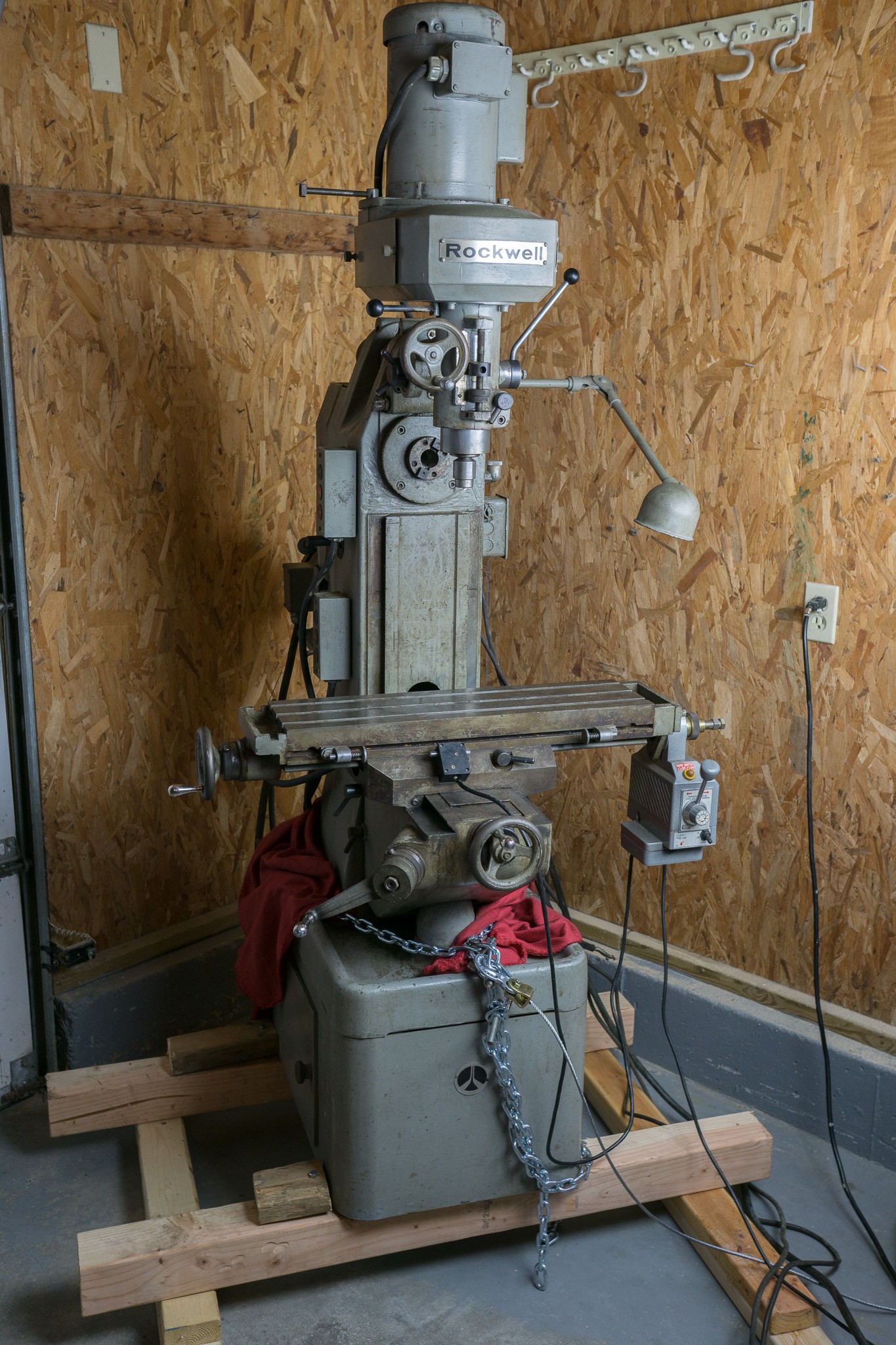
Rockwell Milling Machine Rebuild
Rebuilding a Rockwell 21-122 Horizontal/Vertical Milling Machine
 polyfractal
Become a Hackaday.io member
Already have an account? Log in.
Just one more thing
To make the experience fit your profile, pick a username and tell us what interests you.
Pick an awesome username
hackaday.io/
Your profile's URL: hackaday.io/username. Max 25 alphanumeric characters.
Pick a few interests
Projects that share your interests
People that share your interests


 charliex
 youkito1991
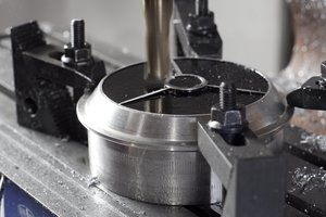

 Rory
Rory
I own one!