Introduction
The project is based on an ESP8266 WiFi SoC. This reads the water level using an LM393 analogue amplifier connected to a home made hydrometer. The output is via an SSD1306 OLED display and an email to the user.
Hardware
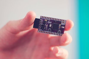
The ESP8266 module chosen is the WEMOS D1 Pro. It is well packaged, comes with plenty of shields and is fully self sustained with only a micro USB power supply required (LiPo Shield available) to power the whole project. It is fully supported by Arduino IDE, which makes life VERY easy.
The analogue output of the LM393 is connected to the A0 ADC input on the ESP8266. This is mapped against 0-100 to provide a % and spurious readings are standardised to either 0 or 100.
Electrode erosion is a common problem with these cheap LM393 devices, so I decided to experiment and use a piece of copper cable from electrical 'twin and earth' cable. The cable then needs to be extended to the breadboard with the LM393, I used some chocolate strip and speaker cable for this. The electrodes are buried in a groove chiseled into the lower trunk and stapled in place. A trailing hose is connected to ease watering.
The screen is a monochrome 0.96" OLED with a built in SSD1306 controller, connected via SPI. This uses more wires than I2C but provides a faster refresh, which is good for the regularly updating pointer.
Software
The software is a mixture of standard libraries, and my own code. Initially it starts by connecting to the WiFi, then the OLED screen is set up with a background drawing of the gauge outline. The Gauge code was grabbed from the link at github. you will notice that there is a lot of reference to AFR throughout the gauge code, as the original gauge was generated for an automotive application, this does not impact the operation. There is a red and green LED connected to the D4 and D2 pins. RED flashing indicates poor WiFi connection, Red Solid signifies water empty, this is easy to see from the other side of the room. Green flashes for 50ms each time a reading is taken and serves as a 'active' indication. To improve the fidelity when refilling the water the reading is taken every 100ms, so an incrementing 'flashCounter' counter and modulo ensures that the green LED only flashes every 10 cycles, to provide a more meaningful indication.
The Gsender header is used to send the gmail. Instructions are at the links. It seems complicated to set up but was reliable. You need to reduce the security of the GMail account, so I generated another account to use for the ESP8266. A mail sent flag stops an email being send every cycle and checks for the water to be topped up.
Developments
1) A further development would be to use a micro water pump fed off 5v likely through a logic level MOSFET. This could automatically fill the tree stand up from an adjacent reservoir. Risk is immediately generated through the possibility of inadvertently pumping of the entire reservoir over the living room floor!
2) WiFi tree light control. Likely to run out of I/O on an ESP8266, so would need an I/O extender chip eg MPC3008, or use the OLED to give system messages and remove the LEDs.
Issues
1) I have had an enduring problem with the WiFi not connecting properly, this may be an issue with my router, rather than the software. The router seems to provide the connection as soon as the ESP is turned on but the connection is not fully made.
2) The range is poor from full to empty. Probably more prototyping with the bared length / proximity of the electrodes would help.
Core Code (Sketch)
// TreeMail - Christmas Tree Hygrometer
//
// By Edward Hammock


#include "ESP8266WiFi.h"     // WiFi Header file
#include "Circular_Gauge.h"  // Header file for the Gauge
#include "Gsender.h"         // Google Mail header file

// Declare Variables
int sensor_pin...
Read more »
 Rodmg
Rodmg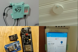
 arttupii
 cafelizardo
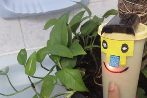
 Siddhant Choyal