 Ben
BenI recently got a bunch of new prototype boards back from the PCB fab. I've been assembling them and redesigning the enclosure to work with the new boards.
I've moved to having each backplane board containing 3 slots on them, they have a single i2c bus that links across the top of the board. One board then connects to the 2 breakout pins that pass the bus into one of the backplane slots to the dedicated MQTT master board for communication with greenskeeper.
I also broke out the USB passthrough to a micro-usb socket, which then has a cable that runs to a dedicated 13 port USB hub, which is then plugged into greenskeeper for managing the console servers for each caddy (if present)
After playing around with it a bit, I think I need to look at incorporating a USB hub onto each backplane board instead of having a dedicated USB hub with cables running from each backplane unit to it.
For now it is suitable for testing the core functionality out, and I will redesign the boards to have a FE1.1S on each one so they are linked, and pass through the first USB hub via a breakout cable that plugs into greenskeeper. This will reduce the number of cables required between the boards considerably.
Here are some pictures of the new enclosure, including the new PSU mounting plate and backplane boards.
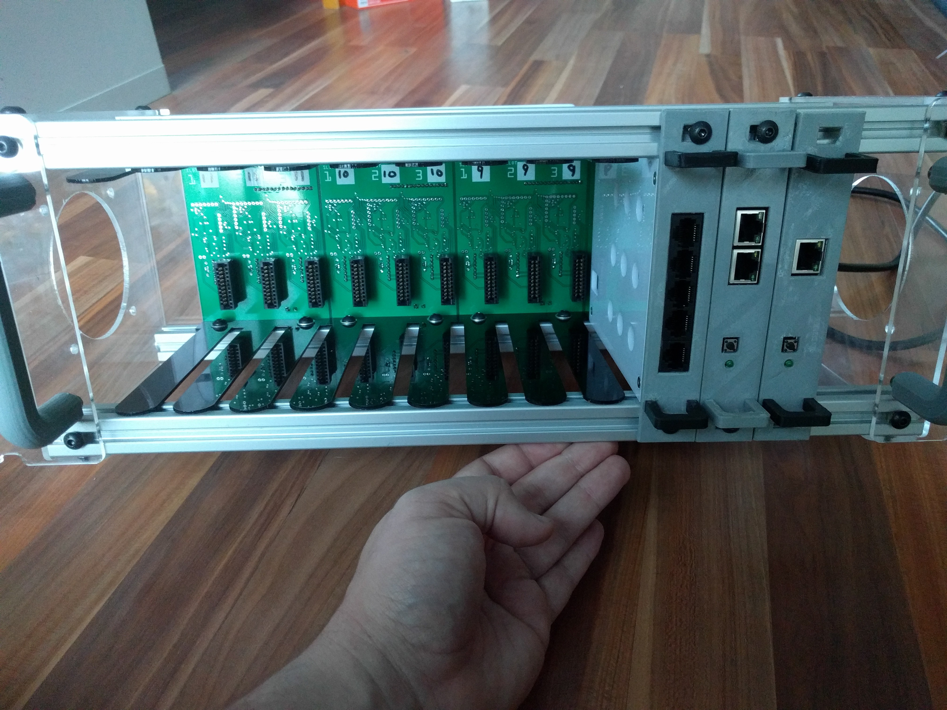
First up, front view. I've laser cut all the enclosure parts to reduce the amount of 2020 extrusions that are required. I also laser cut some slot dividers to aid in caddy insertion so that the backplane and control cards insert correctly.
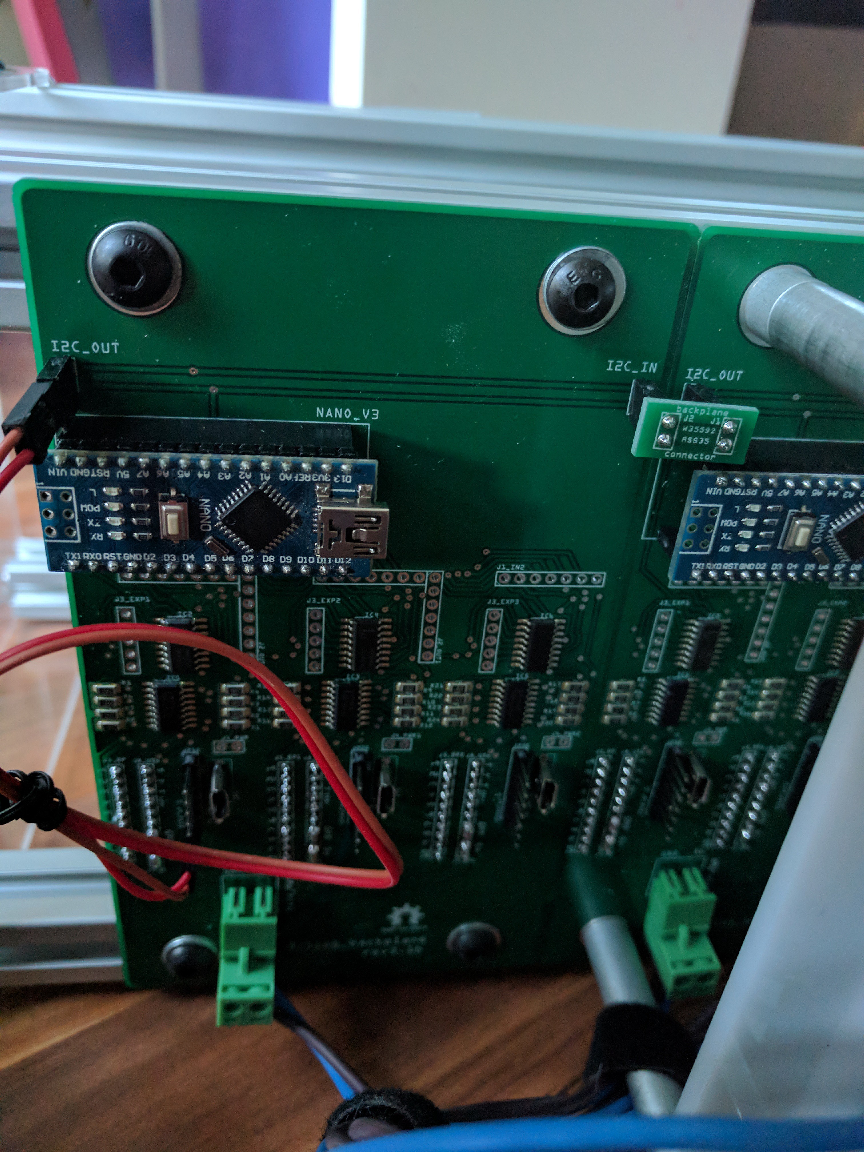
Next up, a pretty poor view of the backplane board. I left a lot of pin headers on this version for testing, but these will go away in the next version with incorporated USB hubs. I'll also be converting the nano to a dedicated ATMega328 instead of requiring the nano. This should free up some space to fit the USB components, and make things a bit more streamlined. I'll also re-orient the power connector so that its horizontal, to make it sit better.
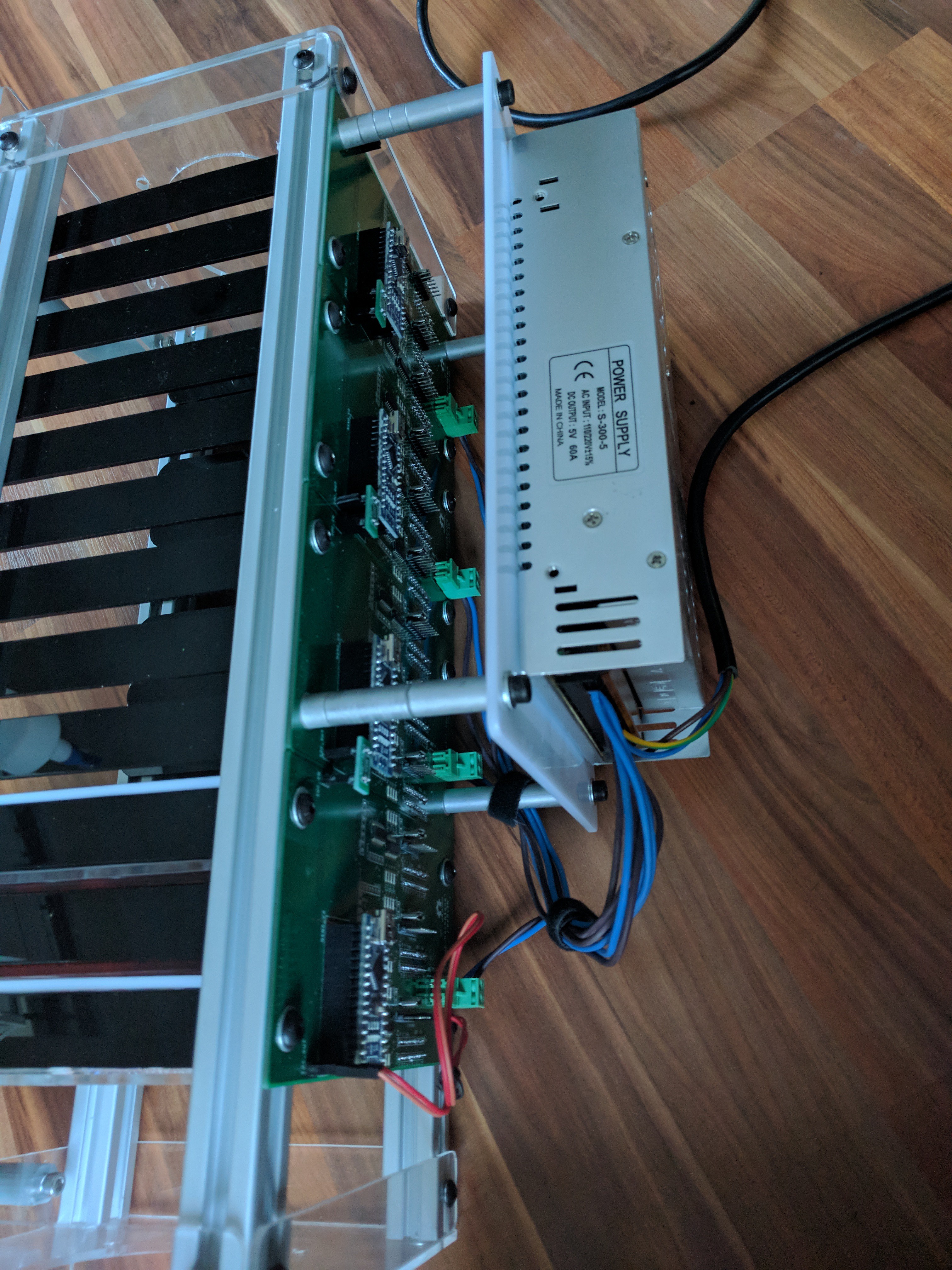
And the Power supply mounting plate. Instead of using 2 slots up for the power supply like I originally intended, I decided to move it to the back of the unit and beef it up a bit. This is a 5v 60A PSU, should be plenty. Average RPI requires 1-2.5A, the rest of the components are relatively low powered too so might be able to get away with 2-3 shacks running off a single PSU.
Part of the whole process is also trying to isolate the caddyshack from any other networking. To do this I am looking at adding a small router of some sort as a dedicated resource for the caddyshack. Currently I'm evaluating an Orange Pi R1, it has 2 ethernet ports (only 100m though :( ) and wireless. I'm looking at either OpenWRT or ZeroShell as the software running on it, it depends which one has the best support for wireless.
The caddyshacks would then have their own dedicated subnet with DHCP, using NAT to access the internet via the "WAN" port which would connect to your existing network and get an address via DHCP from your home router. Wireless can be used either for client connections directly into the caddyshack network, or for SBCs that want to utilise the wireless instead of cables. You could even configure your home router with a static route to the router in the caddyshack so you can access it from your home network, or use a host route on your desktop/laptop to access it.
I'm also evaluating other boards like the ODROID HC1 to use for a storage controller, hopefully post some information about this soon with how it would be used.
Discussions
Become a Hackaday.io Member
Create an account to leave a comment. Already have an account? Log In.