 lion mclionhead
8/20/2016
The amplifier section
The decision after decades of planning to make something custom out of old MOSFETS, reading comments on the DROK, & a brief dreams of tubes, was to invest in a bog standard STA540 from $parkfun. It would also be the most compact.
8/27/2016
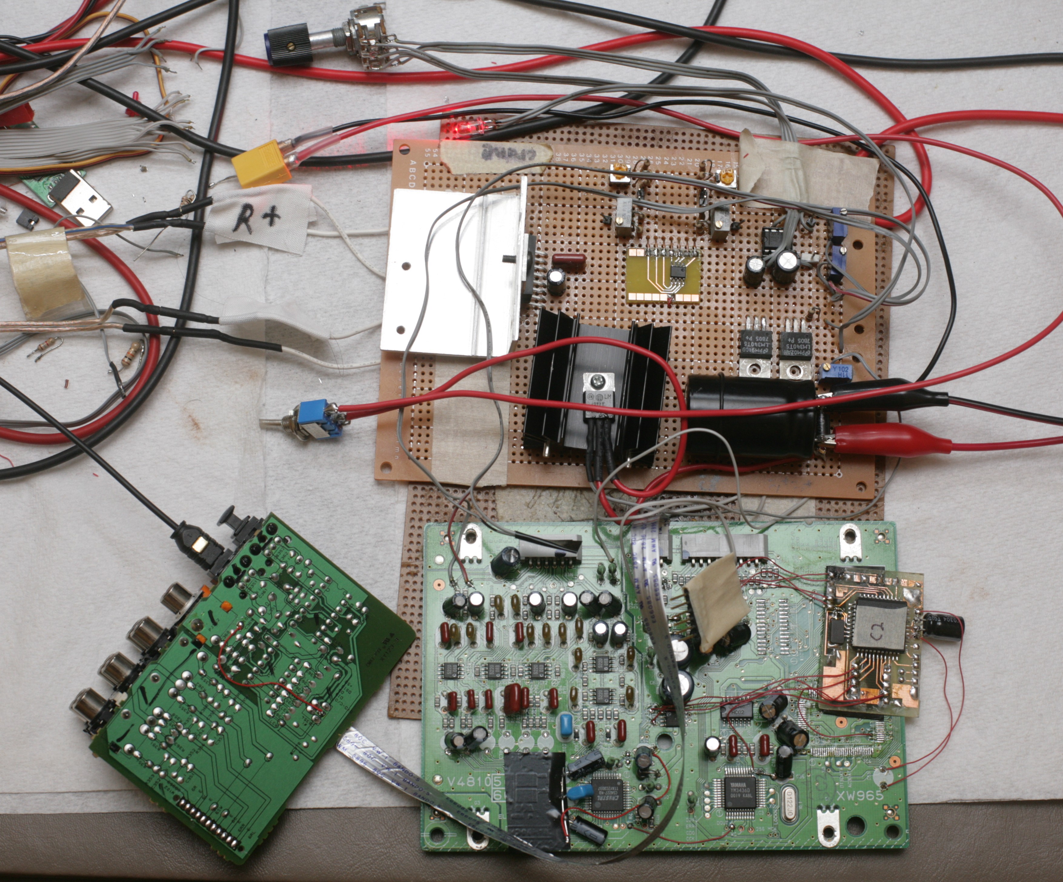
Reworking the HTR-5230 begins
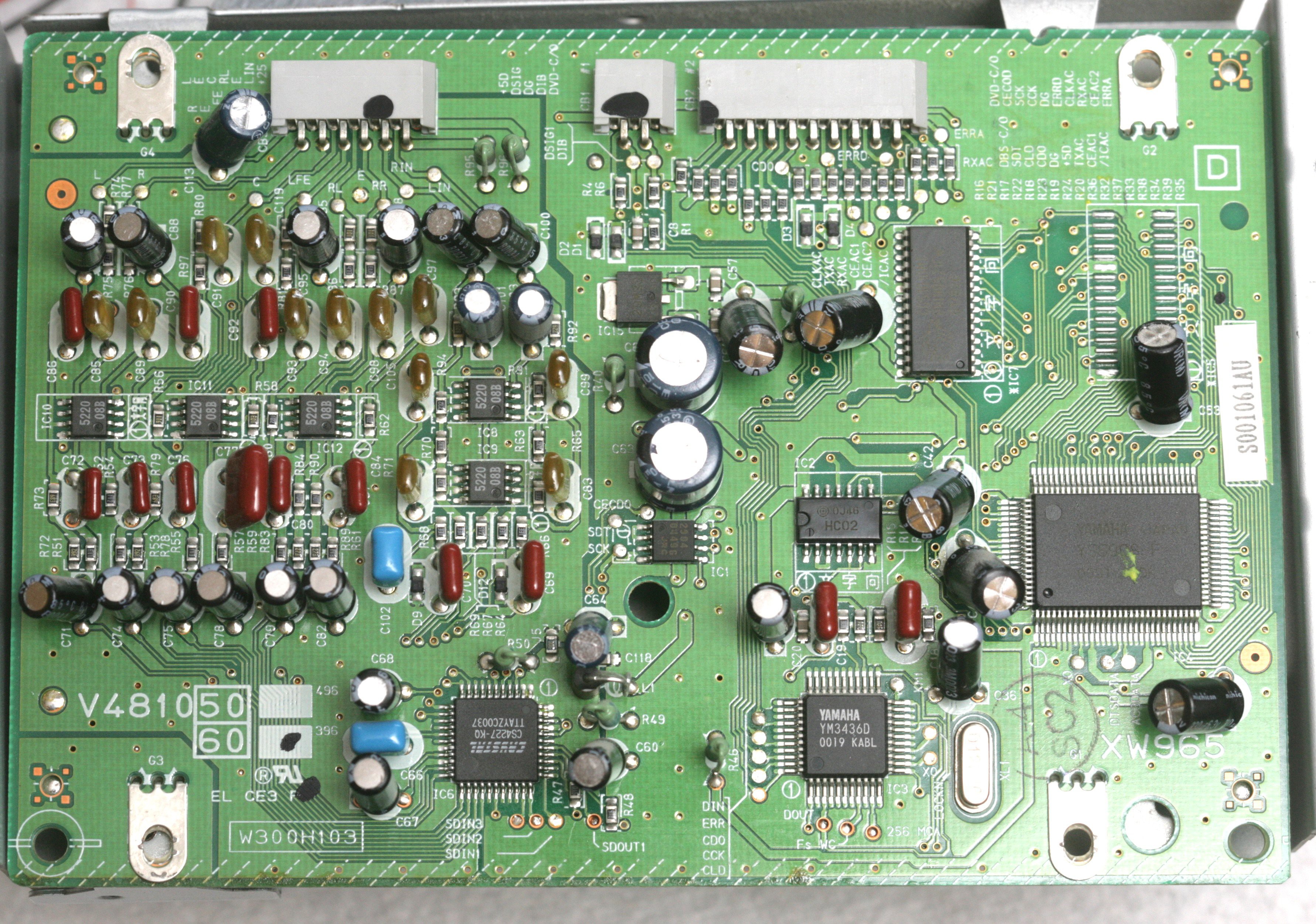
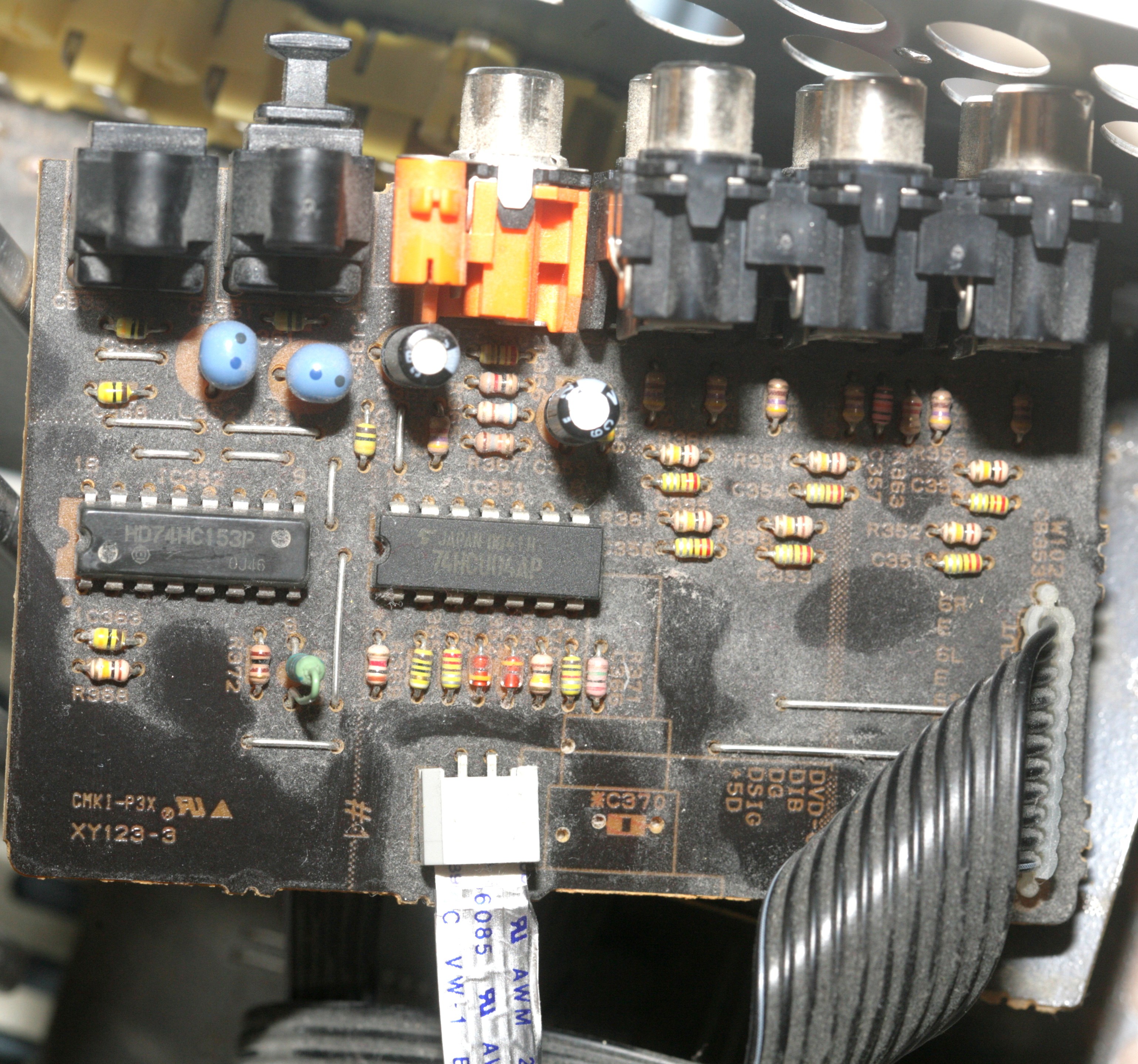
Analog input proved too noisy. Reviewing the available datasheets for the HTR-5230 revealed the TOSLINK input could be extracted from it for use in another amplifier. The dual TOSLINK inputs were multiplexed into a single input by a simple voltage level. The single input went into the 1988 era YM3436 which converted it to I2S. This was configured by simple mode select pins.
The I2S went into the 1999 era CS4227 which had the DAC. The I2S was routed through the undocumented YSS908 to process the special effects. It could easily be hotwired to bypass the YSS908.
Everything uses 5V at a fairly high current. The CS4227 is configured for SPI. You can see data on the AD1/CDIN line when changing inputs. CDOUT isn't connected. CCLK goes at 100khz & sends 2 bytes when changing inputs. CS is erratic.
The initialization merely sets the attenuation registers. Their default is 127
reg value
4 -> 5
5 -> 5
6 -> 13
7 -> 13
8 -> 13
9 -> 23
The analog out after attenuation is 1.8V-2.8V. It goes to a butterworth filter recommended in the datasheet, but requiring +/- 25V. The butterworth filter needs a fairly high current & generates a lot of heat. The final output is -3.3 - 3.3V. The filter GND needs to be raised for it to have a chance.
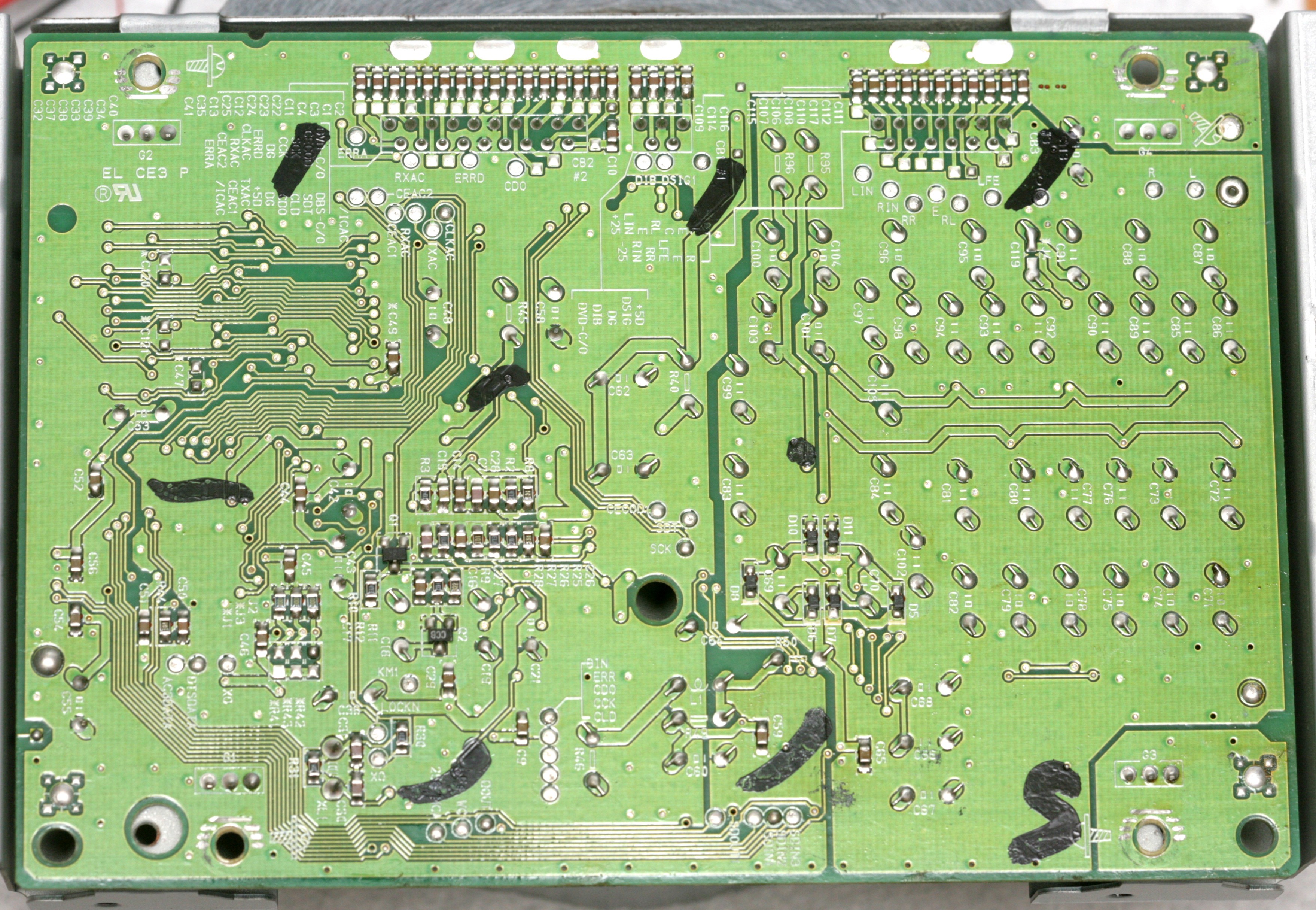
The filter ground fortunately had very few connections. The 1st step was disconnecting the filter ground from the logic ground, which required lifting a few caps & cutting a few traces, but it was perfectly happy.
The next step is reversing the direction & removing some caps before raising filter GND to 5V. Also very important to look for any other parts which might explode.
9/4/2016

It came together manely as expected. The mane difficulty was getting the STA540 to work. For the STBY pin, the datasheet says MAX V for play is 1.5V, MIN V for standby is 3.5V. In reality, STBY needs to be pulled up for play & grounded for standby. Trap for young players.
The CS4227 needed a substitute microcontroller to initialize it, as expected. Quite a few more registers had to be set in a certain order to initialize it, which weren't sniffed by the oscilloscope. The YM3436 needed a few pins biased, as expected. Traces had to be cut. The mane challenge was both chips needed reset to be low for a certain time after powering up. The YM3436 wouldn't initialize if reset started out high.
The complete DAC took a lot of power. The +25V rail wouldn't initialize when connected to the 10V regulator. The 10V came from a 5V regulator with a 5V virtual ground, but the +25V rail started below 5V. The regulator seemed to detect the +25V rail starting below its virtual ground of 5V & shut down by some kind of SCR latchup. +25V ended up connected to the raw 12V. The 5V virtual ground initialized properly.
The total quiescent current with the power amplifier & DAC was an insane 0.35A. The 2 5V regulators got quite hot. The STA540 needed a large heatsink. The mane problem when playing sound was the DAC needed its ground connected directly to the ground on the STA540. Connecting it anywhere else on either the signal or power ground caused distortion. Connecting to either signal or power ground on the STA540 worked, so the DAC being a DAC went to the signal ground.
This circuit definitely made less 60Hz hum & noise than the HTR-5230. The Baxandall from Elliot sound projects worked much better than the EQ in the HTR-5230. Despite doubts, the decision was made to max out both treble & bass. Put in a single turn pot for the bass to make it easier, but left treble as a multiturn since it would never change.
The distortion experienced on 8/21 ended up being from the op-amp. The LM324...
Read more »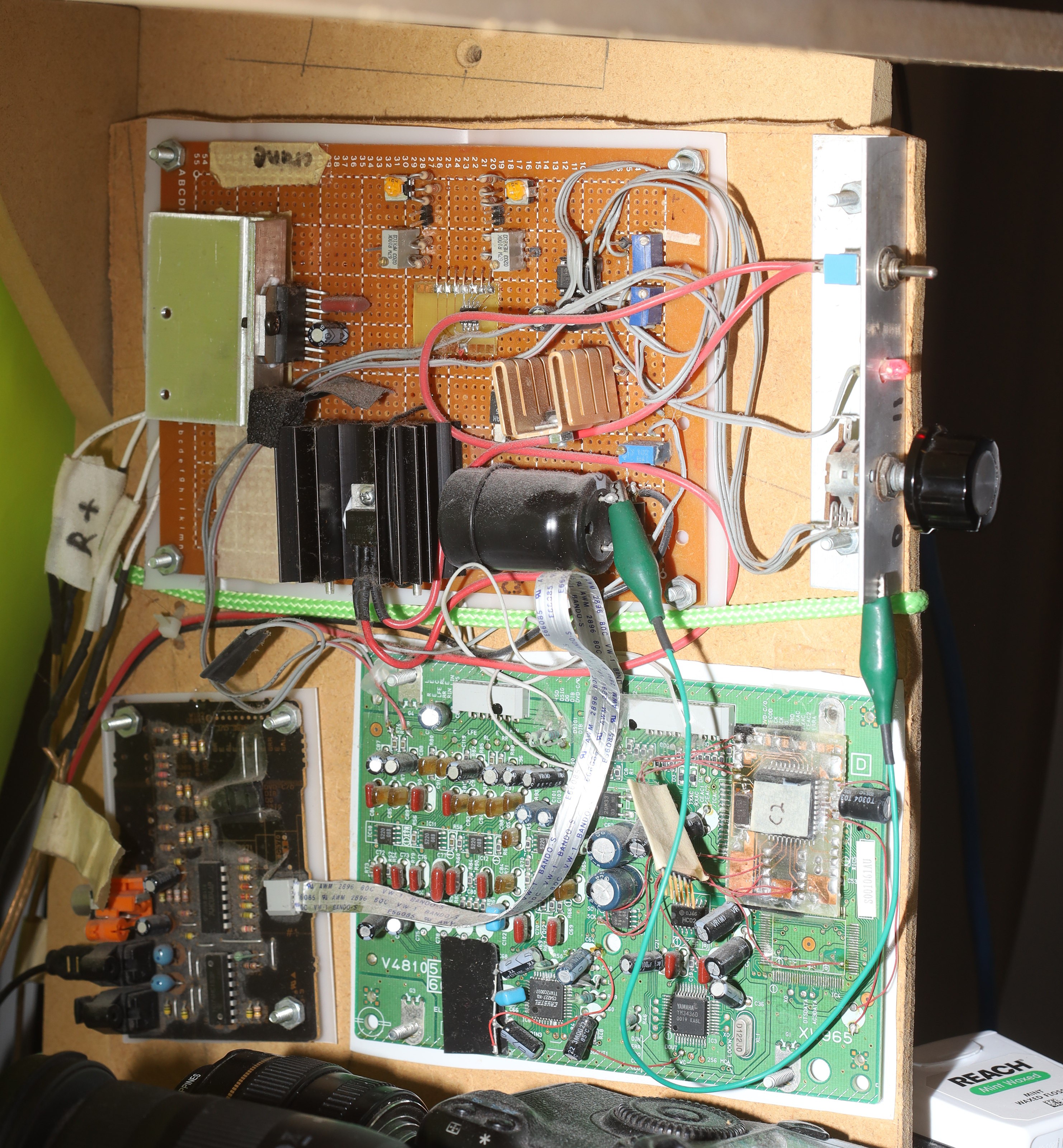

 Todd
Todd
 Nick Sayer
The Thai government offers various incentives and programs to attract foreign investment in the real estate sector, making it an appealing market for investors https://yoohoohomes.com/news_detail/phuket-real-estate-market.