Close
0%
0%

GPS Talking Clock

Accurate time without a display

Similar projects worth following
Starting from
$184.99
nsayer has 2293 orders / 162reviews
Ships from United States of America
I was inspired to start this project by listening to the USNO Master Clock telephone feed on New Year's Eve 2017/2018. My wife complained that it was the wrong timezone, but there are no time-talkers left in Pacific time. I glanced over at one of my GPS clocks at midnight and it struck me that there was no reason I couldn't make my own talking clock for either live use with a speaker or perhaps even as a dialup service.

The timekeeping aspect of this project is very simple. While the GPS clock project had granularity down to the 10th-of-a-second, which required some interpolation, this clock only requires one second granularity. There is a need to keep a sub-second timer, but we'll get to that later. Getting time from a GPS receiver requires handling the serial I/O as well as the PPS output from the receiver. We can use the PPS as an interrupt to create the leading edge of the tick and beep sounds (so that they're as accurate as possible) as well as marking the second-start for synchronizing the software activities.

Like all of the time-talkers that have come before, we want to use sampled audio rather than attempting to use voice synthesis. The limited vocabulary of the clock makes that the path of least resistance. 8 kHz 8 bit µ-law encoding provides "telephone" quality level for the audio. The bad news is that the 32 kB of flash available is obviously insufficient for the number of samples required. Storing the audio on an SD card or SPI flash chip gives us plenty of storage, and by using FAT storage, we can configure and access the storage quite easily. This also potentially allows field replacement of the samples, so that people could customize the voice (even the language) however they like.

We use the same XMega32E5 controller we used in the v5 variant of the GPS clock. The XMega32E5 has a 2 channel DAC that we can use to play back the audio samples from the SD card or SPI flash chip. We can use one of the timers configured for 8 kHz as a clock for the DMA controller to trigger updating the current DAC value so that playback can be done largely in the background (we have to double-buffer the sample reads to insure the playback remains seamless, but that's only 1k of RAM out of the 4k available). When reading the values in from the flash, we also need to convert the µ-law samples into 12 bit (actually, 16 bit, but the hardware drops the bottom 4 bits) unsigned values. This is, however, fairly straightforward.

The actual audio format is 10 second blocks. Every second is marked by a 10 ms "tick" and every 10 seconds there will be a 3/4 second beep. The leading edges of these are synchronized to the PPS of the GPS receiver using the PPS ISR. We configure one of the timers to output a 1 kHz square wave on one of the pins of the controller, and we simply turn that output on early in the PPS ISR and in the outer loop turn it off either 10 ms or 750 ms after the second.

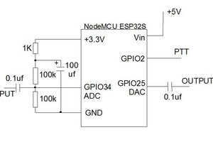
The audio circuitry takes the 1 kHz square wave output and runs it through an RC low-pass filter. Then it is mixed with the output of the DAC and the sum fed into an audio amplifier and speaker. The power amp is an LM4871, which is a push-pull style amp designed to drive a small speaker from a low voltage supply.

The SD card slot or SPI flash chip is simply connected to the SPI interface. The directory layout is top level directories "ZONE" "HOUR" "MINUTE" "SECOND". Inside of each of the hour, minute and second directory are files named 0-60 (0-24 for hours, and only every 10 for seconds), each of which are an audio snippet. Inside of "ZONE" are files with two letter names, the first of which is a timezone (Pacific, Mountain, Central, Eastern, Alaskan, Hawaiian), the second of which is either S for standard or D for daylight. There will also be a "U" for UTC. Every 10 seconds, the playback consists of the appropriate ZONE file, then hour, minute and second. The intended scripting is "At the tone, Coordinated Universal time will be 23 hours, 59 minutes, 50 seconds." The first second of each 10 second block is reserved for the previous block's mark tone. Seconds 2 through 6 are for the "ZONE" file, then one second for each of the time files, which means the whole thing should end just before the 9th second.

There is a simple set of DIP switches on the board to configure the desired timezone. The system simply continuously generates the audio stream,...

Read more »

Adobe Portable Document Format - 67.45 kB - 12/12/2021 at 18:35

Preview
Download

sch - 460.52 kB - 12/12/2021 at 18:35

Download

brd - 129.16 kB - 12/12/2021 at 18:35

Download

Adobe Portable Document Format - 74.26 kB - 09/28/2019 at 17:32

Preview
Download

sch - 494.34 kB - 09/28/2019 at 17:32

Download

View all 6 files

  • 1 × Assembled board
  • 1 × Laser cut wood case part set
  • 28 × #4 brass nuts
  • 1 × 20 kΩ audio taper panel mount pot
  • 1 × knob for the volume control

View all 13 components

  • New GPS receiver

    Nick Sayer12/12/2021 at 18:41 0 comments

    If you've been following any of my other GPS project you'll know that the Venus838LPx-T is being EOLed. SkyTraq's replacement is the PX1100T, which has a number of improvements. It does, however, necessitate both hardware and firmware changes.

    On the hardware side, there are fewer parts required. The module itself injects 3.3 volt active antenna power, so there's no longer a need for an external bias-T. It's also a castellated edge board style module rather than an LGA-69 package (which is a lot easier for me to deal with).

    On the software side, the serial baud rate is 115200 rather than 9600, and some of the messages are in the form $GNxxx rather than $GPxxx, which reflects the quad constellation support.

    One disadvantage is that there is no FIX LED output pin, so for backwards compatibility I've implemented the equivalent behavior (on for bad GPS, blinking at 1/2 Hz for good) on one of the controller pins. You could argue that it's redundant, given that one of the debug pins is simply on for bad and off for good GPS. The benefit to it before was that it was from the receiver module itself, and thus independent of the controller.

  • No more preamp

    Nick Sayer09/28/2019 at 17:28 0 comments

    I finally figured out why the preamp was always necessary and how to remove it.

    The problem was quite basic. I had always wanted to put a cap in parallel with the feedback of one amp or the other to act as a low pass anti-alias filter for the digital audio. I calculated the correct value as 2200 pF but wound up buying 0.022µF caps (that is, 22,000 pF). In working on Evil Simon, I figured this out and have been using 1000 pF caps ever since with great success.

    Well, it turns out that if you configure the LM4871 for unity (it's actually 2x because of the push-pull design) gain with a 1000 pF cap in the feedback path, you can remove the pre-amp entirely and everything is just fine. The volume range is quite reasonable and at low volume, it sounds clean.

    To do this with the existing boards, replace C25, R4 and R8 with 0Ω resistors, remove IC5 and C26 and populate C20 with 1000 pF. This effectively connects pin 3 of the volume control directly to the output of the balance control and moves the LPF feedback cap to the LM4871. If you're populating a new board, you can leave off C21, C22, R13 and R14 as they're not used for anything, but if they're already installed there's no harm in leaving them.

    This will wind up being v1.4.

  • v1.3.1 - SPI flash

    Nick Sayer08/18/2019 at 01:01 0 comments

    The v1.3.1 hardware works perfectly. There are some tweaks to the programming process, obviously, and a few tweaks to the code, but programming the flash chip with "flashrom" both from a mac with a BusPirate and from a Raspberry Pi using its SPI interface is fairly straightforward. In fact, the Pi can successfully program the chip with an SPI clock of 20 MHz, which makes it much, much faster. If you're building your own version, you should check that flashrom supports the flash chip you want to use. I didn't do this beforehand and had to add support for it to flashrom for it to work right. The clock itself doesn't really care about what kind of chip it is, as long as a "0x03" read command works and it supports a maximum SPI clock of at least 16 MHz (it also obviously has to have at least enough storage for all of the audio samples).

  • µ-law audio compression

    Nick Sayer08/05/2019 at 18:17 0 comments

    There was never any reason to compress the audio back when it was on µSD cards. But flash rom SOIC chips aren't anywhere near as large. That's ok, though. You can get 16 MB flash chips, and the audio for the talking clock didn't need half that much space. But in the interest of reducing the BOM cost even further, I've investigated whether going from raw 12 bit audio to 8 bit µ-law encoded audio would work. It turns out it works just fine - the audio is half the size but the fidelity to my ear is exactly the same.

    µ-law audio uses an exponential system for the quantization step. The closer to zero (µ-law is inherently signed. Our audio system requires unsigned values, so we also convert to unsigned as part of the decoding) a value is, the less difference there is between adjacent values. Values far from zero have a much wider separation.

    The conversion used by the firmware is compatible with the mu-law codec in sox, which makes it particularly convenient to prepare audio samples. You just turn whatever your source audio is into raw 8 bit single channel 8kHz µ-law audio streams.

  • µSD -> SPI flash

    Nick Sayer08/03/2019 at 03:09 0 comments

    One thing that bugs me a little is that the micro SD cards are a significant expense. Not only do you have to buy the card, but you have to buy the socket for it too.

    In principle, there's no real need for removability here. While it would simplify field updates of the audio samples, it doesn't make doing field updates impossible. In addition, it makes the whole system more reliable, since mechanical jolts can't loosen the chip like a card.

    We'll stick with using petitFFS and a FAT filesystem, but the diskio layer is far, far simpler - you send a 3 (the read command), a 3 byte start address, and then you read until you're done (yes, in principle you can read the whole chip with one command).

    To program the chip, you have to either erase the controller's flash (to keep it from trying to talk to the flash) or hold it in RESET. Since the controller's programmed with PDI, it's necessary to use a separate programming interface for this. I simply chose the traditional AVR ISP pinout, substituting !CS for the !RESET pin. When used for AVR programming, the normal sense of the MOSI and MISO pins are actually reversed - the AVR chip acts like an SPI slave, listening on MOSI and talking on MISO. My intention is to write a little program for the Raspberry Pi's SPI interface to just burn an image file into the chip using just 6 wires hooked up to my 6 pin pogo adapter. Turns out there's a program called "flashrom" which will already do this, and it too supports the Raspberry Pi SPI interface. But it also supports various USB peripherals, so I'm going to try using a Bus Pirate v4 on my mac for this. If that doesn't work, the fall-back is the Pi.

  • More volume control tweaks

    Nick Sayer01/25/2019 at 05:19 0 comments

    The latest design moves the volume control to after the preamp, which cuts down on the low-volume noise. I also changed the balance control to a through-hole trimmer so it'll be easier to adjust. I also found a .1" SIP trimmer that can be used for a board-mount volume control, or replaced with wires to a panel mounted volume control.

  • Volume control tweaks

    Nick Sayer12/17/2018 at 00:10 0 comments

    I did some experiments on the volume control system. Two volume controls for separate control over the speech and beeps is a bit unsatisfying, so I've changed it to instead be a balance control followed by an overall system volume.

    While I was at it, I discovered that cutting the preamp gain in half made for better volume control range and less noise. I'm pretty happy with the result.

    The only question left really is whether to make the volume control external or not. It's definitely more convenient to have a knob, but that adds to the cost compared to a board mounted trimmer.

  • More firmware options

    Nick Sayer09/06/2018 at 21:31 0 comments

    One customer recently asked for a mode of operation more like WWV than the USNO. That is, 59 ticks and one beep per minute, with a single time announcement in the last ten seconds. 


    To accommodate that, there is now a WWV macro in the firmware, so this mode is a compile-time choice.

    I’ve also been asked to make a 12 hour AM/PM clock.

    You can actually do that by just re-recording the hour audio samples. You can do that by just copying the 12 sample over the 0 and copying 1 through 11 over 13 through 23. That would give you a purely 12 hour clock. If you want AM/PM as well, then you have to either re-record all the hour files to add AM or PM... which would result in a script like “At the tone, Pacific Daylight Time will be 4 PM, 23 minutes, 10 seconds.” If you’d prefer “4 hours, 23 minutes, 10 seconds PM,” then firmware work would need to be done to support it.

    Frankly, I like the easy way, and not just because I’m lazy. It just seems a more natural way of reading it. 

  • Laser cut wood case

    Nick Sayer02/20/2018 at 06:59 1 comment

    My friends at Steamy Tech helped me finalize the design for the laser cut and engraved wood case that's coming soon to the store. It's 4" x 4" x 2", and by housing the speaker in a cavity that size, the bass is really accentuated and the whole thing just sounds a whole lot better.

    The DIP Switches are accessible through a cutout on the back panel (you mount the DIP switches on the opposite side as the components for using the case), and the big red button on the top has the obvious function.

    They've got a few pressing items on their schedule, so it'll be a week or so before the inventory of cases is available, but I think it'll be worth the wait.

    EDIT: The case doesn’t have any viewports for the LEDs, but it turns out you can see the FIX LED through the speaker cone. If it’s not blinking, then GPS isn’t working. That’s the number two reason (after the speaker being turned off) that the clock would be silent. 

  • Chimes and configuration

    Nick Sayer02/06/2018 at 17:27 0 comments

    I've added support to for optional chimes and hour-strokes at the top of the hour.

    That sort of begs the question as to how to enable/disable the chimes temporarily when you don't want them.

    The DIP switches would seem the natural mechanism, but there are only four of them, and I don't want to just keep piling them on.

    It occurred to me this morning that I could simply add a config file to the top level of the SD card. That would allow configuration of, say, 8 different timezone/DST settings with the DIP switches and set one switch aside to turn the chimes on and off.

    EDIT: The chimes now can actually be on any minute you like, with optional per-hour STROKES at the top of the hour. The SD card now comes programmed to perform full-on Westminster Quarters.

View all 20 project logs

  • 1
    Usage instructions

    Install a CR1220 battery in the backup battery bail. This battery is optional, but if present will help the GPS receiver by preserving the satellite almanac across power cycling.

    Insure a properly formatted and loaded µSD card is installed in the slot.

    Adjust the trimpot near the board-mounted button to the center of its range. This trimpot adjusts the balance between the ticks/beeps and the sampled audio. Once you can hear the audio, adjust this pot for best balance.

    Connect a GPS antenna to the SMA jack and plug a 2.1mm barrel connector with 5 VDC center positive to the power jack. The FIX LED (LED3) near the corner of the board and the GPS diagnostic light (LED1) should come on. As soon as the GPS receiver gets a fix, the FIX LED should start blinking at 1/2 Hz and the GPS diagnostic LED should go out. At some time a few seconds later, the clock should begin playing the audible timecode.

    You can push the button any time (except during chiming) to turn the audible timecode on or off.

    At any time, you can change the DIP switches to select the desired timezone. You can also turn switch 3 on or off to enable or disable the chimes. The chimes will only sound when the audible timecode is muted.

    The default time zones available:

    • 0 - UTC
    • 1 - Pacific Time
    • 2 - Mountain Standard Time (no DST - Arizona)
    • 3 - Mountain Time
    • 4 - Central Time
    • 5 - Eastern Time
    • 6 - Hawaii Standard Time (no DST)
    • 7 - Alaska Time

    If at any time LED2 lights, that indicates an error accessing the flash filesystem. The best suggestion is to recreate the filesystem image and reload it.

  • 2
    Assembly instructions

    The board comes as a "quick kit" with the DIP switches unattached. If you're installing the clock in the laser-cut case, then install the DIP switches on the bottom of the board (opposite the components). Otherwise, it's up to you which side. If you prefer, you can connect some other switching mechanism up. The top 4 holes (nearest the center) are the switched pins. Shorting any of these to ground turns the switch "on."

    For mounting in a case, you can connect a remote switch up to the 2 pin terminal near the on-board switch.

    The speaker jack should be connected directly to a 4Ω or 8Ω speaker. The speaker terminals are a bridge output configuration - do not connect either one to ground. The bottom terminal is positive (but it doesn't really matter in practice).

    For faster restarts after power outages, install a CR1220 battery under the battery bail on the board. This battery will likely last many years, as it is not used except when the board is unpowered (and even then the draw is very, very small).

  • 3
    Laser-cut wood case assembly

    Attach the speaker loosely to the front panel with 4 3/8" screws, lock washers and nuts. Once all 4 screws are loosely attached, tighten them using a figure X pattern.

    Solder 4 wires to the speaker and button terminals. Use 22 gauge wire 6 inches long (to facilitate easier case assembly).

    Attach the board to the back panel with 4 5/8" screws, 1/4" spacers, lock washers and nuts. Orient the board so that the DIP switches are visible through the cut-out with the switch numbers immediately above. The components should be facing upwards.

    Attach the volume control to the back panel with its washer and nut. Use a 20 kΩ audio-taper pot.

    Insert the button firmly through the hole in the top panel (the top panel doesn't have a front or back side).

    Solder the speaker wires to the speaker terminals and the volume pot to the volume terminals. Make sure that the counter-clockwise end of the pot goes into the CCW hole on the board. The center is the wiper and the other terminal is the CW end.

    Solder the two switch wires to the switch terminals, then bend those terminals down to about a 60 degree angle against the switch body.

    Now is a good time to test the circuitry. Connect an antenna and apply power. Wait until the FIX LED (bottom left corner) begins to blink and the GPS LED (bottom of the two paired near the top middle of the board) goes out. Within a few seconds of that, the voice announcements should commence. Push the button to silence them and again to resume. Change the DIP switches to verify they function. Disconnect power and antenna for remaining assembly steps.

View all 5 instructions

Enjoy this project?

Share

Discussions

Mike Yurick wrote 02/26/2019 at 00:35 point

I like your idea, especially the old-school style speaker grill.

  Are you sure? yes | no

NobodyYouKnow wrote 01/21/2018 at 19:00 point

Ah. Thanks. That explains why I was not finding it from the usual sources. Of course, it is a BGA device. I haven't tried to push my SMT skills that far yet. :-)

  Are you sure? yes | no

Nick Sayer wrote 01/21/2018 at 19:49 point

it’s actually an LGA - there are no balls. So you just paste and place it the same as if it were a QFN - there are just more pads underneath. 

  Are you sure? yes | no

NobodyYouKnow wrote 01/22/2018 at 13:25 point

Thanks for the correction. That might not be so bad, then. An LGA I can handle. Are you aware of a commercial source that sells in the onesie-twosie range?

  Are you sure? yes | no

Nick Sayer wrote 01/22/2018 at 16:11 point

SkyTraq will sell in small quantities. I just buy large ones for the quantity pricing and to better amortize shipping cost.

  Are you sure? yes | no

NobodyYouKnow wrote 01/21/2018 at 18:49 point

What is your source for the Skytraq / Venus 838LPx-T? I'm having a bit of trouble finding it as a bare chip. Thanks!

  Are you sure? yes | no

Nick Sayer wrote 01/21/2018 at 18:51 point

I buy them a tray at a time from SkyTraq in Taiwan. 

  Are you sure? yes | no

Dan Maloney wrote 01/19/2018 at 19:37 point

Hey, this looks pretty cool. I'd like to write it up for the blog -- do you think you'll get the audio problem sorted out soon? A video of the clock in action would be a big bonus, too. 

  Are you sure? yes | no

Nick Sayer wrote 01/21/2018 at 19:28 point

Absolutely. 

I will say that in this case the video looks almost identical to the picture. 😁 (but the video can carry the audio - I get that).

The audio problem at the moment is a quandary. There shouldn’t be any reason it’s so low, which suggests I’ve just made some other dumb error.

I’m fairly sure I’ll be ordering a second prototype board run this week and I’m confident that one will be correct. 

  Are you sure? yes | no

Nick Sayer wrote 01/28/2018 at 06:12 point

I've added a YouTube video with the improved audio (now that that mystery has been solved).

  Are you sure? yes | no

Similar Projects

Does this project spark your interest?

Become a member to follow this project and never miss any updates