 Keith
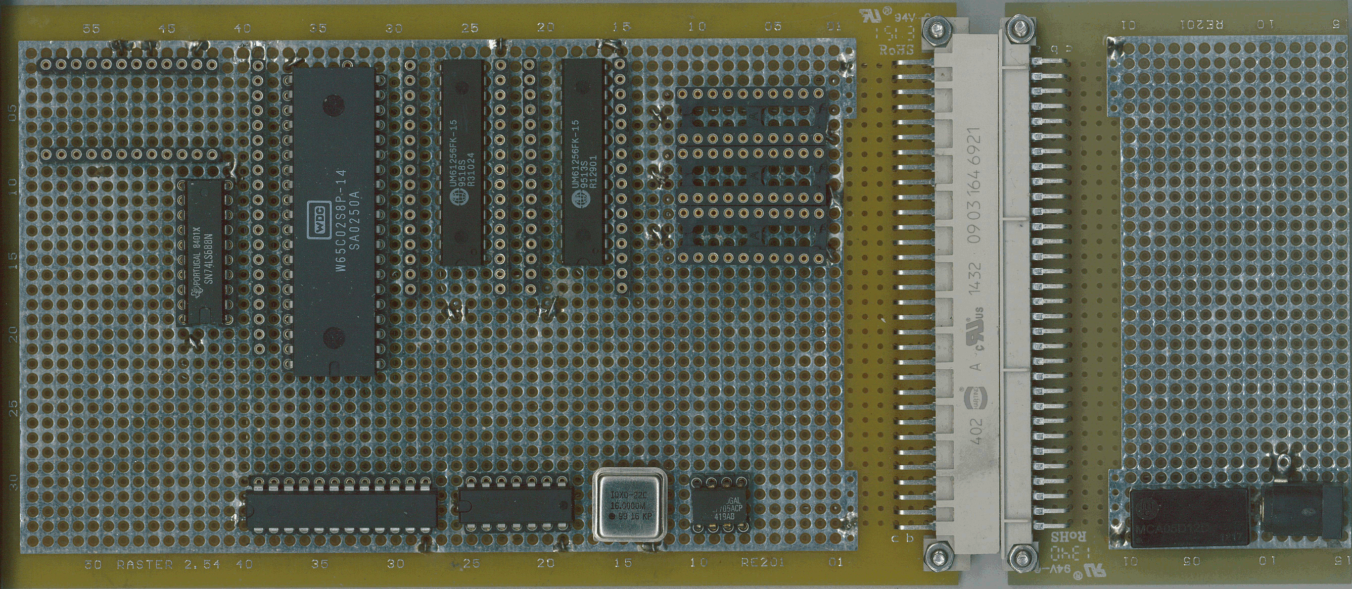
KeithMy initial placement. I have the 32K RAM chips under the ROM sockets. This simplifies wiring a lot. They are directly soldered to the PCB, because they won't be changed and they are nowadays cheap enough to not bother recovering.
On the right is a simple board I use to take 5V from a common wall-wart power supply with 2.1mm inner pin, and apply it to the STEbus power pins. There is also a 5V to 12-0-12 volt DCDC converter, which drives the +/- 12V rails.
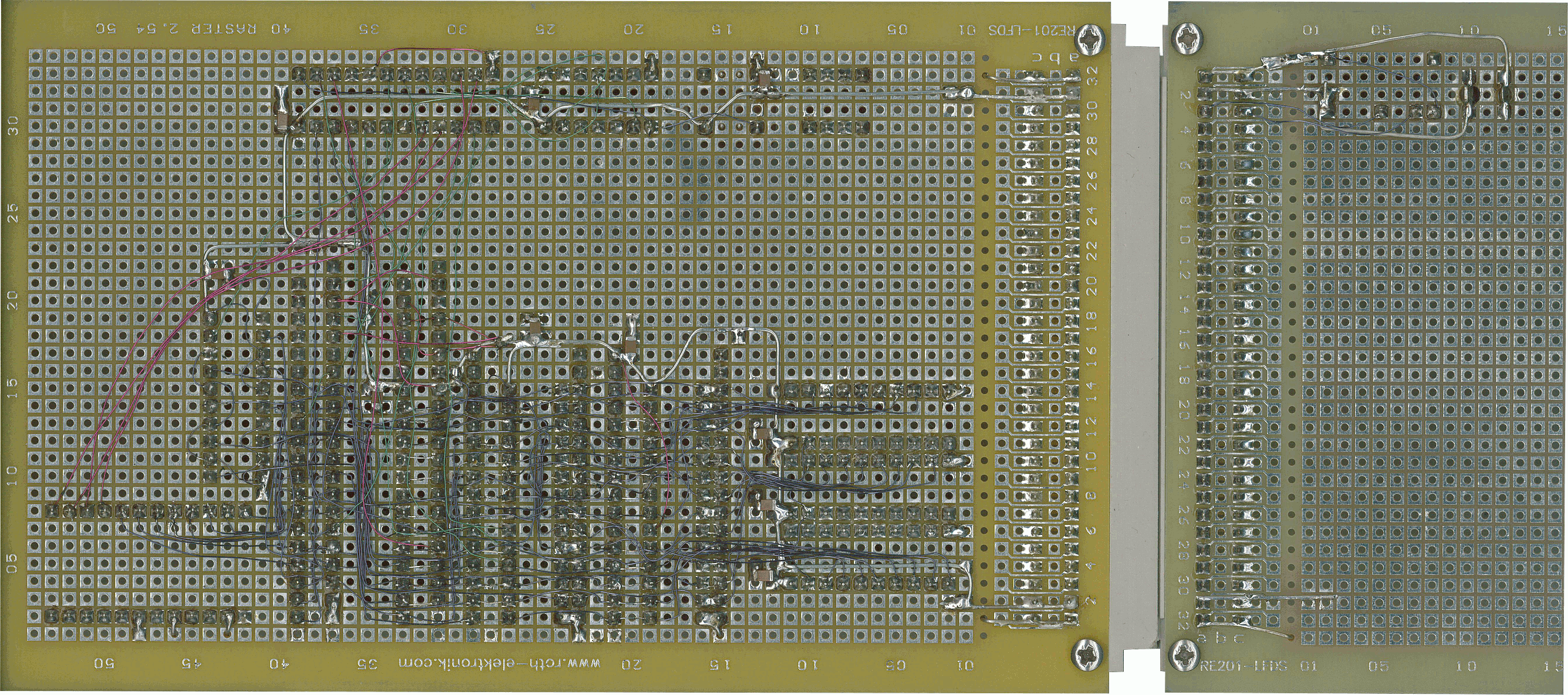
An early shot of the underside, before the bus signal wires were fitted. I use surface mount decoupling capacitors because they were easy to fit and take little board area.
Note that most small DCDC converters have poor regulation. They are probably as sophisticated as a 555 oscillator driving a small transformer and a rectifier. Yes they may give the nominal voltage at the working load, but the data sheet graphs usually show the voltage goes up at lighter loads. This may well be above the absolute maximum rating of the chips they drive. Some kind of upper voltage limiting is advisable.
Also note that they are not very tough. Accidentally putting an RS232 buffer in the wrong way round can overload and destroy small converters, as I found by experience. Order a spare, to be prepared.
Discussions
Become a Hackaday.io Member
Create an account to leave a comment. Already have an account? Log In.