 lion mclionhead
Started a schematic of the CAD GXL-2400 7 years ago. Finally finished the part showing the amplifier section, but not the power section.
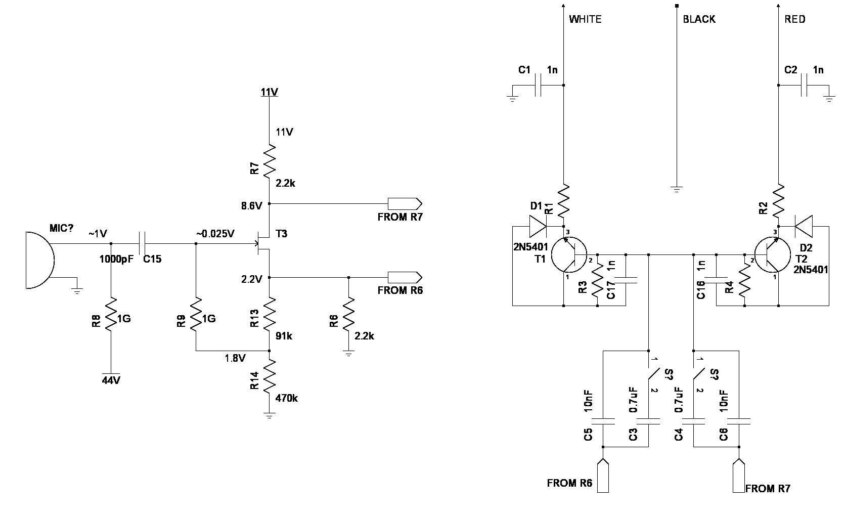
The salient points are the switch is a bass rolloff. Probed the voltages of the 1st stage. From ohms law, we have 1mA going from 11V to ground, through T3. T3 presents a 5.8k resistance in silence. R13 & R14 pass a few uA & R6 passes the rest.
Technically, it's 2.2k + 5.8k + 2.2k in series. When the transistor passes more current, the 8.6 drops & the 2.2 rises. When the transistor passes less current, the 8.6 rises & the 2.2 drops, instant differential pairs.
It would work with just a 12V supply. R7 & R6 could go directly into an op-amp circuit & then an ADC.
There's a decent description of an amplifier very similar to this one, which has a capacitor shunting R13.
Lions long dreamed of powering it off a more reasonable voltage besides 48, but every test says all the components are sized for exactly that voltage. Going lower causes the transistor bias voltages to become unstable & would require a major redesign.
Suspect phantom power is going away & all future microphones are going to be USB with the ADC inside the can. With only brief shopping & very limited specs online, would say the current bottom of the line are 48khz 16 bit USB mics. Very expensive USB mics probably do 24 bit 192khz.
The absolute limit could be considered a battery powered ADC inside the can, with optical output. The problem with integrated ADC's is they all require digital signals inside the can, so the debate between external & internal ADCs probably hasn't been settled.
A ground up circuit to reach line level inside the can probably would be more useful than an external preamp. Having said that, experience with the AK4524 showed no meaningful noise from the digital side but all the noise from sources outside the microphone can. At minimum, it would just need a direct conversion of the I2S data line into a 3Mhz optical signal, a booster to 48V, & a pot sticking out of the can.
Discussions
Become a Hackaday.io Member
Create an account to leave a comment. Already have an account? Log In.