Close
0%
0%

Micro TV-B-Gone

The Micro TV-B-Gone is based off of Adafruit's original TV-B-Gone kit, except made to be as small as possible, using an LIR-2032 coin cell.

Similar projects worth following
I based this project off of the Adafruit TV-B-Gone kit. I wanted to start getting into using surface mount components on my projects, and seeing as the TV-B-Gone was my first foray into soldering, I figured that it would be a great project to work on.

The device takes a rechargeable LIR-2032 battery, and is activated pressing the single button on top. It will run through all TV power codes, and then go into a low power mode, waiting for the next button press. The battery will last around 40 full cycles, before being reduced down to 3.5 volts.

Hardware:

Microcontroller: Attiny85

Battery: LIR-2032

Features:

The version of the device shown is the v1 device, I've ordered the v2 device (all components on top, only 3 emitters) and will hopefully have it assembled soon.

The Attiny85 is in sleep mode for the majority of the time, and only runs when the button is pressed. 

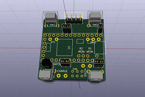
The device is exactly 1"x1" in size, only slightly larger than the coin cell battery. 

The device has a single red indicator LED, that flashes once every time an IR signal is emitted, then flashes three times in quick succession when the transmitting is done.

The device has 3 side facing IR emitters, which cover nearly a 180 degree field of view. Originally I had all six IR emitters populated, but combined they drew 130mA when on, which is above the recommended 70mA in the battery datasheet. Although 70mA is listed as the maximum constant current, I didn't want to risk damaging the battery. 

I plan on running some more in depth battery life tests when I have access to an oscilloscope. 

MicroTVbGone_r2.brd

Board file for the 2nd revision board.

brd - 863.19 kB - 01/05/2018 at 22:45

Download

MicroTVbGone_r2.sch

Schematic for the 2nd revision board.

sch - 440.48 kB - 01/05/2018 at 22:44

Download

brd - 879.37 kB - 01/04/2018 at 16:14

Download

sch - 446.55 kB - 01/04/2018 at 16:14

Download

  • 3 × Osram High Power IR Emitter IR emitter
  • 1 × Attiny85 Microprocessors, Microcontrollers, DSPs / ARM, RISC-Based Microcontrollers
  • 1 × SMD 100uF Capacitor decoupling cap
  • 1 × SMD 0.1uF Capacitor decoupling cap
  • 3 × SMD NPN Transistor

View all 10 components

  • Improvements

    Nicholas Junker01/04/2018 at 16:44 0 comments

    Improvements for future iterations

    In the future, I would like to add a battery life indicator light to let the user know when the battery is nearing the end of its life. Currently I just keep a mental note of how many times I've used it, and double check with a multimeter. 

    I would also like to remove the two caps from the bottom of the board, as they are scarily close to shorting out from the coin cell. By removing the 3 unpopulated IR emitters on the top, I can make room for this and the battery life indicator.

    The final improvement would be to build the battery charging circuit into the board, and add a micro-usb connector so you don't have to purchase an external LIR-2032 charger.

View project log

Enjoy this project?

Share

Discussions

oshpark wrote 07/18/2018 at 18:45 point

Awesome project!

  Are you sure? yes | no

daniel g. wrote 01/17/2018 at 12:32 point

Is there anywhere we can download the firmware from?

  Are you sure? yes | no

Nicholas Junker wrote 01/17/2018 at 18:25 point

The github is linked under the Project Inspiration link on the left. 

  Are you sure? yes | no

neeek wrote 02/14/2019 at 07:32 point

The firmware in the github is for the standard version that has an 8mhz xtal.

To change the firmware to use an internal clock, what changes need to be made ?

Is it just the fuses that need to change ? or something in the code as well

  Are you sure? yes | no

Nick Sayer wrote 01/16/2018 at 23:57 point

Have you considered adding a boost converter to try and get more of the life out of the battery?

  Are you sure? yes | no

Bastiaan wrote 01/17/2018 at 09:37 point

Maybe also a charge circuit for the coin cell is possible, I think there's board space enough. Curious what @Nicholas Junker thinks about it.

  Are you sure? yes | no

Nicholas Junker wrote 01/17/2018 at 18:27 point

I'm currently working on a charge circuit for the coin cell - pretty sure I'll have enough space for it. 

  Are you sure? yes | no

Nicholas Junker wrote 01/17/2018 at 18:33 point

The Attiny85v (low voltage version) runs down to 2.7 volts, so I don't need a boost converter. I would definitely use one if I was using a typical coin cell, but I'm using a rechargeable coin cell, and don't want to bring the voltage down below the safe discharge voltage. 

  Are you sure? yes | no

Nick Sayer wrote 01/17/2018 at 18:36 point

ah. I missed that it wasn’t a primary cell. 

  Are you sure? yes | no

Michael Cullen wrote 01/07/2018 at 13:13 point

What is the battery life like on this? You imply you count how many times you’ve used it. How much did all 6 emitters reduce it?

  Are you sure? yes | no

Nicholas Junker wrote 01/07/2018 at 15:59 point

Using all six emitters reduced the battery down to 3.5 volts after 20 cycles. I forgot to mention that having the six emitters drew 130mA when on, which is over the 70mA maximum current draw listed on the battery data sheet. Even though the battery could probably handle the 130mA (since it isn't a constant current draw) I didn't want to risk damaging it. 

  Are you sure? yes | no

Similar Projects

Does this project spark your interest?

Become a member to follow this project and never miss any updates