Close
0%
0%

The PVC Scanning Tunneling Microscope

An easy-to-build scanning tunneling microscope.

Similar projects worth following
When I built my first Scanning Tunneling Microscope (STM) back in grad school, it was very expensive and took a lot of time to build. When I starting teaching physics at the college level, I wanted have my students build a STM in a couple of lab periods. Our first student-build STM in 2008 didn't work very well, but we have improved it every year since. We now use John Alexander’s simple STM piezo design and National Instruments data acquisition boards. I published an overview of the project in the December 2015 issue of "The Physics Teacher" but this page will focus more on the building process. Dan Berard's STM project here on HACKADAY gets better results but requires more machining.

The main driving principles for this project are

  • Resolution in the nanometer range - graphite would be nice.
  • Build time of about six hours.
  • Setup, troubleshooting, and testing in three hours.
  • Cheap components.

In terms of tooling, the project needs are modest - a hacksaw, a drill, soldering iron, hot glue gun, etc.  A band saw and a drill press are nice to have but not essential.

In terms of parts (excluding the data acquisition system), the cost is fairly low at under $100.  The data acquisition system is the expensive part of the project.  The National Instruments boards cost about $350.

Additional details are on my studentSTM page at my university.  The link is on the left side of this page.

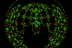
The best resolution recorded by my students so far is 5 nm.  I have push it a bit further on my own and gotten fair HOPG pictures.

  • 1 × All components are listed in Instructions

  • Another Sample

    Tom Ekkens03/29/2018 at 04:48 0 comments

    US Penny

    Preparation: A cheap option for the third sample is a new US penny. A new penny is usually still shiny so it only needs to be cleaned with methanol to get the finger oil off it. It can be mounted to a washer but the simplest method is to just placed it on the STM sample holder and let gravity hold it down. 

    Imaging: Two images of the penny are shown below. In all cases, the flat area just above the date is where the images were taken. On the top is the penny as it appears when imaged using a light microscope. This microscope has a magnification of 800 times so the field of view (top to bottom) is about 210 μm. Ridges from the manufacturing process are all in the same direction, but the ridge separation is not consistent. At this size, the penny is quite similar to the aluminum foil sample. On the bottom is an image taken by an atomic force microscope with a field of view (top to bottom) of 15 μm. At this scan size, ridges and bumps are both visible. The ridges are spaced at about 4000 nm and the bumps are 700 nm and smaller.

    Two pictures taken from the STM are shown below. Both pictures are taken at approximately the same location, with the same bias of +1 V, and with the same the same scan speed (300 mS per line). The image on the top has a scan size of 4200 nm and the image on the bottom has a scan size of 600 nm. Both images have their share of randomly-sized ridges but the smaller scan size shows a number of smaller bumps – some as small as 20 nm in diameter.

  • Optional Improvements to the studentSTM - Optical Camera

    Tom Ekkens02/15/2018 at 20:03 0 comments

    During sample positioning and approach, it is nice to have an optical image from the tip/sample region.  Recently, a borescope with a short focal length has become available on Ebay.  It is called the “3 in 1 USB Ear Cleaning Endoscope Earpick Waterproof Borescope Inspection Camera” and costs $11.90.  While it only has 640x480 resolution (0.3 MP), the 1.5 cm focus distance is a required feature.  Windows 10 recognizes this camera without any additional drivers and includes software to view the live image.

    Integration to the STM is very easy.  A 7/32” bit can be used to drill a hole or holes in the PVC housing at a point where both the tip and the sample can be seen.  One good position for the hole is as close to the flange as possible, angled slightly down to point at the end of the tip, and rotated about 90º from the sample access hole.  Another good position for the hole is right at the tip level without any tilt on the hole.  The first picture below shows the housing just after the hole has been drilled.  The second picture is from the borescope showing the tip approaching the DVD sample.  The borescope is mounted in the angled hole.  On the far side of the tip, the untilted hole is visible.

  • Another Sample to Use

    Tom Ekkens02/04/2018 at 21:27 0 comments

    Aluminum Foil - Shiny side.

    The previous sample - a piece of DVD - is easy to image but only has good repeated features at the 740 nm level.  Another sample is needed for additional size scales. 

    Preparation:  A cheap option for the second sample is a piece of aluminum foil.  It is mounted to a washer so that the magnet in the stage will hold it down.  In the picture, I have made two additional electrical connections using silver paint but this really wasn't necessary.  I have mounted it so the shiny side is up.

    Imaging:  Two images of the aluminum foil are shown below.  On the top is the foil as it appears when imaged using a light microscope.  This microscope has a magnification of 800 times so the field of view (top to bottom) is about 230 μm.  Ridges from the manufacturing process are all in the same direction, but the ridge separation is not consistent.  Some of the ridges are vary wide but some smaller ones are in the range of 10 to 30 μm.  On the bottom is an image taken by a scanning electron micrscope with a field of view (top to bottom of about 3600 nm.  This scan size matches the largest field of view that the STM has so the picture should be similar.  At this magnification, there are smaller lines and bumps in the range of 100 to 300 nm.

    Two pictures taken from the STM are shown below.  Both pictures are taken at approximately the same location with the same field of view (2500 nm) and the same scan speed (400 mS per line).  The image on the right was taken with a bias of 600 mV and is completely worthless.  The image on the left was taken with a bias of 3000 mV and has excellent detail.  A major ridge can been seen with additional small ridges and bumps in the range of 100 to 300 nm.  Other bias settings of -600 mV and 2000 mV were tried but were not as good as the 3000 mV image.

  • Samples to use on the STM

    Tom Ekkens01/23/2018 at 00:56 0 comments

    Because the STM requires a current through the sample, anything we want to measure must be conducting.  This can be accomplished by either using only metal samples or by coating a non-conducting sample with metal.  Since the coating process is expensive, we will restrict ourselves to conducting samples that are easy to obtain.

    DVD+R.

    As mentioned in the operation section, a small piece of a DVD+R disk is the best sample to start with.  It is easy to prepare, cheap, and images well.

    Preparation:  Cut into a DVD-R disk with a pair of scissors. Try to remove the clear plastic layer from the DVD, leaving the top of the disk with the label and the foil layer on it. Cut a section out just smaller than a #10 washer. Place it, foil side up, on the washer. Attach it down using conductive tape or glue. Make a good electrical connection between the foil and the washer.

    Imaging:  Two images of the DVD are shown below.  The top image is the DVD as it appears when imaged using a light microscope.  This microscope has a magnification of 800 times or about 1.2 million pixels per meter.  Since the image is 675 pixels high, the spacing of the lines is determined to be 731 nm.  This matches the expected value of 740 nm from the DVD specification.  The bottom image is an image taken by the STM with a side length of about 2500 nm.  The line spacing is again about 740 nm.  The quality of the STM tip makes a large difference in the image.  A sharper tip would make the troughs in between the ridges more visible.  Several other parameters also make the image appear different.  The scan speed for this image was about 500 mS per line.  If we move too fast, the image blurs but if we don't move fast enough, external noise is worse.  The bias for this image was 600 mV.  

  • Update to Data Acquisition System

    Tom Ekkens01/15/2018 at 03:37 0 comments

    As the PCI connectors disappear from computers, the price on the National Instruments PCI-6229 card is beginning to fall. In January 2018, Ebay had several listings for sale in the range of $375. If a computer with a PCI connection is available, this now the preferred solution. In addition to the card, a way of connecting to the microscope is needed. A single $50 “12 foot Shielded VHDCI Male Cable” http://www.daqstuff.com/100768_vhdci_mm_cable.htm can be purchased and cut in half. Headers can be added to the following conductors and plugged straight into the STM. The wire color is correct for the 100768 cable only.

    J2

    Plug1

    Wire Color

    1

    22 – X

    Center bundle: White with pink stripe.

    2

    21 – Y

    Tan with yellow stripe.

    J5

    Plug0

    Wire Color

    1

    21 – Z

    Tan with yellow stripe.

    2

    55 – Ground

    Yellow with brown stripe (paired with 21).

    3

    68 - Tunnel Current Read

    Purple with pink stripe.

    4

    34 – Tunnel Current Ground

    Pink with purple stripe (paired with 68).

    5

    22 – Bias

    Center bundle: White with red stripe.

    BigEasy

    Plug0 – Motor

    Wire Color

    GND

    18: (D GND) Ground

    White with blue stripe (paired with 52).

    STEP

    17: (P0.1) Motor step

    Tan with brown stripe.

    DIR

    52: (P0.0) Motor direction

    Blue with white stripe (paired with 18).

    The connections are explained more fully in the electrical section of the build instructions. The only change between this list and the connections listed in the electrical section is that the digital ground for the stepper motor moves from pin 50 to pin 18. The reason for this change is that pin 50 is close to pin 52 on the connection box but pin 18 is twisted with 52 in the cable. This solution moves the total cost of the data acquisition system down to just over $400.

  • 1/8/18: Final Update.

    Tom Ekkens01/08/2018 at 18:54 0 comments

    The operation steps have been added.  Have fun with it.

  • 1/7/18: Build Instructions are complete.

    Tom Ekkens01/08/2018 at 03:58 0 comments

    I have up-loaded all of the build instructions as of this evening.  The only thing left to add is a basic operations guide.  That will come in a few days.

View all 7 project logs

  • 1
    Mechanical Construction

    Design Parameters

    This microscope is designed to be built by students in a few lab periods. In most places, the trade-off between resolution and cost has been tilted toward the cost side. The priority list, from highest to lowest, is:

    • Build time of about six hours.
    • Setup, troubleshooting, and testing in three hours.
    • Cheap components.
    • Modest tooling requirements.
    • Resolution in the nanometer range.

    Part List

    One ¾ slide repair coupling – Home Depot part number: 032888605046

    Two ½” plug MPT - Home Depot part number: 049081143145

    One small magnet (8mm x 3mm) - Home Depot part number: 095421070459

    One piece of circuit board material (0.037”, FR4, Single, 1oz) – Ebay

    One spool of 30 gauge magnet wire or ribbon cable - Ebay

    One 27 mm Piezo Transducer Sound Disc (20mm PZT) - Ebay

    One phenolic standoff 3/4” long by 1/4” diameter - Ebay

    One DIP socket (any size) - Ebay

    One 1¼ to 1½ reducer bushing - Home Depot part number: 034481062271

    One NEMA 17 stepper motor - Sparkfun part number: ROB-09238

    One brass 2mm to 5 mm motor coupler - Ebay

    2-56 threaded rod - Ebay

    One 7” Hose Clamp - Home Depot part number: 078575179957

    Tooling List

    Hand drill or drill press.

    3/4” drill bit.

    Vise or drill press clamp.

    2-56 drill and tap set.

    Hot glue gun.

    Soldering gun and solder.

    Scissors, side cutters, etc.

    Hacksaw or bandsaw.

    Razor blade.

    Multimeter.

    1. Housing Preparation.

      1. Disassemble the ¾ Slide Repair Coupling into its three component pieces (cap, slider and housing).
          • Try to leave as much grease on the orings and sliding surface as possible since it will be required for normal operation.
          • Clean the grease off any surface that you will be gluing to.
      2. Using the drill or drill press and the 3/4” bit, cut the sample access hole just below the threads of the housing.
          • During drilling, use safety glasses, a vise, and observe all safety precautions.
          • In the picture, the hole was drilled a little too close to the flange and cut into it. This configuration still works, but it looks messy.
          • The edges of the hole should be smooth so the orings do not catch on them.

    2. Slider.

      1. Prepare the plugs.
        1. Cut a rectangle of thin circuit board just smaller than the plug’s outer diameter and hot glue a magnet to the center of the non-copper side.
        2. Solder a six inch length of wire to the circuit board.
        3. Hot glue the circuit board to the plug as shown on the left side of the picture.
        4. Drill and tap a 2-56 hole in the exact center of the other plug as shown on the right side of the picture.
        5. (Optional) Use a saw and cut the hex flange down to ½ its height.
      2. Prepare the slider.
        1. Cut the non-o-ring end off the slider so it is 50 mm long and smooth the edges of the cut.
        2. Press the plugs into each end of the slider.
          • The plug with the foil and magnet goes into the end nearest the o-rings.
          • The plugs should fit tightly so they will not need to be glued into position.

    3. Piezo and Cap.

      1. Use a ruler and razor blade to cut the silver material on the piezo disk into four equal quadrants. The white layer on the piezo disk does not need to be cut. Verify electrical decoupling using an ohmmeter.
      2. Solder on five small wires – one to each quadrant and one to the yellow base.
        1. Use magnet wire with each piece about six inches long.
        2. Try to use as small amount of solder and contact time as possible.
        3. All five wires should be connected to the same side.
      3. Use hot glue the phenolic standoff to the center of the yellow side of the disk.
      4. Attach a tip holder to the end of the standoff.
        1. The tip holder should be made from one section of a DIP socket.
        2. Solder a six inch section of magnet wire to the end of the DIP socket.
      5. Hot glue the piezo to the cap.
        1. A small hollow in the cap may need to be cut to allow the piezo to sit flat on the cap.
        2. The five wires from the piezo should feed up through the hole at the top of the cap.

    4. Prepare the Motor.

      1. Use a 2-56 tap to cut threads in the 2mm end of the motor coupler.
      2. Cut a 25 mm long length of 2-56 threaded rod and thread it into the motor coupler.
      3. Tighten the setscrews in the coupler to attach it to the motor and the threaded rod.

    5. Assemble the STM.

      1. Push the slider fully into the housing and feed the wire through the hole you drilled in the housing.
      2. Screw the end cap unto the housing and feed the tip wire through the hole.
      3. Push the gray reducer bushing onto the housing.
      4. Manually thread the motor assembly into slider until the housing until the motor touches the bushing.
      5. Place the hose clamp around the STM and tighten it to hold the motor to the slider. Except for the green wire and the black connectors on the magnet wire, the assembly should look like the picture below.
          • The clamp will need to be positioned so that the access hole and the motor wires are not blocked by the clamp.
          • Rotate the gray reducer bushing so that the bumps on it do not hit the hose clamp.
  • 2
    Data Acquisition System

    Computer Data Acquisition

    Back when the Scanning Tunneling Microscope was invented in 1981, the CPU in most computers was very slow. The feedback loop needs a bandwidth of about 5 kHz and the CPU couldn’t deliver that speed. The only way to get the desired bandwidth was to build the feedback system using analog electronics. By the 1990s, Digital Signal Processors (DSPs) were available and allowed the most of the feedback loop to be built in software. This allowed much greater flexibility in customizing the feedback system, but was expensive since DSP-based systems cost over $2500.00. In the last 10 years, the speed of the CPU in most computers have increased to the point that the CPU can run the feedback loop in addition to running the operating system, displaying data, and getting input from the user. The requirements for the computer CPU for this microscope are not very demanding by today’s standards. A computer with a dual or quad core CPU should work for this project.

    The heavy lifting from the data standpoint is taken care of by the data acquisition card. Although the cost is reduced by not needed a DSP-based system, the data acquisition card is still the most expensive part of the project. Ideally the card should have the following features:

    • 4 voltage output channels (DACs) with a voltage range of -10 to +10 volts at a minimum of 14 bit resolution (16 bit resolution is preferred).
    • 1 voltage input channel (ADC) with a voltage range of -10 to +10 volts at a minimum of 14 bit resolution (16 bit resolution is preferred).
    • 2 digital out channels.
    • Ability to read and write DC voltages (sound cards don’t do this).
    • Ability to read a single value and write a single value and repeat this combination at a minimum of 1000 times per second (2000 times per second is preferred).

    This feature list is out of the range of most low-cost solutions but the National Instruments Corporation makes boards that fit both the minimum and preferred requirement list.

    Part List - Option 1: Slow but Simple.

    The minimum option costs $378 and is based around the NI USB-6001 device. Each device only has two voltage outputs, so two have to be purchased for this project. Each device includes screw terminals so connection to the microscope is easy. Because the USB interface is not optimized for the single read /single write operations that a feedback loop needs, the bandwidth of the feedback look is slow so image acquisition will take longer.

    Part List - Option 2: Fast and Expensive.

    The preferred option costs $1800 and is based around the NI PCIe-6323 card. This card is available from National Instruments for about $900.00. To connect the card to the electronics, two cables and two breakout boards are needed which add another $900.00 to the total cost. In the picture below, the connections from breakout boards to the microscope are shown.

    There are a couple of ways to lower this bill. The company DaqStuff.com sells cableshttp://www.daqstuff.com/100768_vhdci_mm_cable.htm and breakout boardswww.daqstuff.com/400057_400058_vhdci_m_series_breakout.htm that are much cheaper. Two of these cables and breakout boards have a total cost of $220. Another method to lower the cost is to use the older National Instruments PCI-6229 card. This card uses the older PCI bus and can be found used on Ebay for about $500.00. There does not seem to be a difference in STM operation between the PCI and PCIe cards.

  • 3
    Electrical Connections

    Part List

    One TI Quad Op-Amp (TL074CN) – Ebay

    Four 10 kΩ Resistors – Ebay

    One 10 MΩ Resistor – Ebay

    One Stepper Motor Controller – Sparkfun part number: ROB-11699

    One 12V/1A power supply – Ebay

    Four 9V battery plugs – Ebay

    Four 9V batteries – Ebay

    Breadboard – Ebay

    Part List - Optional

    One 14 pin DIP IC socket – Ebay

    One custom printed circuit board (Amp Rev B) – OSH Park or similar.

    24 Female Headers – Sparkfun part number: PRT-00115

    24 Break Away Headers – Sparkfun part number: PRT-00116

    Assorted Grommets – Home Depot part number: 032076074746

    By using a good data acquisition system, the electrical system is simplified. There are only three amplifiers needed and they all are on a single chip. Two of them invert the X and Y scan voltages and the last one converts the tunnel current into a voltage. A stepper motor controller board is also needed.

    The circuit diagram below shows all the connections. On the left, connections will be made to either the PCIe-6323 card or the USB-6001 device. The pin number for the PCIe card is before the slash and the pin name for the USB device is after the slash.For the best noise results, the amplifier is powered by four 9-volt batteries – two wired in series to provide -18 V and two wired in series to provide +18 V. 

    General Notes

    • Never unplug or plug in the motor while the stepper motor controller’s power supply is on. It will burn out the stepper controller. Make sure you don’t reverse the connections and connect 12 volts to GND.
    • Always unplug the batteries when you are not using them so they do not discharge.
    • Unplug the stepper motor power supply when you are not using the motor so it doesn’t heat up too much.

    Optional Improvement

    To avoid crashing the tip into the sample, it is recommended that the half-step mode be used rather than the full-step mode on the stepper motor. This change is made on the stepper motor controller board by connecting the MS1 pin to +5 volts and leaving the MS2 & MS3 pins connected to ground. In this configuration, four half-steps move the sample through the vertical piezo range. The quarter-step mode could also be used, but the reduced risk of crash does not seem to justify the slower approach speed.

    Build Option 1 – Fast and Noisy.

    The fastest build will run direct wires to each component and build the circuit on a bread board. The best results are obtained by making the wire from the sample to the amplifier as short as possible. A typical system is shown below. The STM is placed on foam to minimize vibrations. The connections to a PCIe card are made through the green and blue breakout boards purchased from DaqStuff. The problem with the above configuration is that it picks up too much noise on the wire from the sample for good resolution.

    Build Option 2 – Custom PCB.

    A better build option is to use a printed circuit board and removable headers. The PCB can be placed closer to the sample which reduces noise and the headers make trouble-shooting the system much easier. The PCB board file can be downloaded from this link and sent to a vendor such as OSH Park for fabrication. In the pictures below, the board and schematic are shown.

    The components should be on the side with the labels and all the soldering should be done on the opposite side. All the headers are identified by a “J” label. Pin 1 of each header is the one closest to the “J” label. The connections to each header are listed below:

    J1

    Tip

    J5 Port 0 - Analog Connection

    1

    21/AO1: Z from Computer

    J2 Port 1 – Analog Connection

    2

    55/AO-GND: Ground

    1

    22/AO0: X from Computer

    3

    68/AI0+: Tunnel Current

    2

    21/AO1: Y from Computer

    4

    34/AI0-: Tunnel Current Ground

    5

    22/AO0: Bias

    J3 Power

    1

    Ground

    J6 Piezo Connection

    2

    +V

    1

    +X

    3

    -V

    2

    -X

    3

    -Y

    J4 Oscilloscope Connection

    4

    +Y

    1

    Z from Computer

    5

    +Z

    2

    Ground

    3

    Tunnel Current

    J7

    Sample

    4

    Ground

    This circuit board can be attached to the housing of the STM right by the sample. The board can be glued to the housing or attached to grommets. In the picture below, the grommets are glued to the housing and hold the board tight enough during operation, but allow it to be removed if needed.

View all 5 instructions

Enjoy this project?

Share

Discussions

Similar Projects

Does this project spark your interest?

Become a member to follow this project and never miss any updates