 Viva Penguinos
DSKY - the Beginning
So that everyone is on the same knowledge level, this section will cover basic knowledge of the DSKY. The image below is the front interface of the DSKY. (Source: The Apollo Operations Handbook)
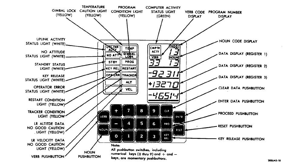
As you can see, the DSKY consist of three data displays. From this point and on, I’m going to refer the data displays as R1, R2, and R3. Furthermore, the DSKY consist of two 7 segment referred to as Noun and Verb. And lastly, the DSKY also contain program number allowing astronaut to know what program the astronauts are on.
Additionally, the DSKY consist of 19 buttons. Labeled as 0-9, Verb, Noun, CLR, PRO, KEY REL, ENTER, RESET. Most of these buttons are self-explanatory but I’ll cover that in future topic. In the upper left there are activity lights letting astronauts some additional information should they need it.
In total the DSKY contains 21 - 7 segment LED's, and 19 buttons. There is much more to explain that aren’t present in this project log. Should more information be explained, I'll be glad to dedicate a log just for the hardware and software of the DSKY.
Choosing the ideal micro controller:
nitially, I started working on this project with an Arduino Uno. Some consideration to using an Arduino Platform was ease of use, programmability, open source, and large community support.It worked initially for testing the proof of concept but then suddenly I ran out of available IO pins. Deciding whether to upgrade from the Arduino Uno to the Arduino 2560, I later decided to find a platform that isn’t based off the Arduino (didn't really like the programming software). After researching, someone suggested me to try the MBED platform. After checking their official site and the platforms that are available, I decided to purchase the Freescale FRDM-KL25Z mainly for the amount of IO pins that are available (In case I plan on adding additional items). The board came in a rather interesting package.

After spending several hours of converting code from the Arduino to the MBED Platform, I managed to get the shift registers to blink the displays on and off. Eventually I do plan on cleaning and optimizing the code for readability and efficiency (My programming skills is mediocre).
R1, R2, R3 Displays:
While contemplating on how to go with this project, I decided to start the project with displays for R1, R2, and R3. To minimize the amount of pins required (which would be absurdly large) I decided to use a BCD – 7 Segment Decoder. This allows me to drive one segment with just 4 pins (Compared to driving it directly with 8 pins). To reduce the amount of pins required I added shift registers into the design. This allows me to theoretically drive as much 7 segment LED with just 3 pins. There are other ways to drive it (IE: Multiplexing) but after weighing the pros and cons. I liked the idea of driving it with Shift Registers to BCD decoders to the 7 segment LED.Initially I purchased a small amount of parts to make sure the theory worked. It started with just 3 out of the 5 segment LED. After prototyping it on a small breadboard I suddenly realized that I ran out of real estate. So I decided to upgrade my breadboard and this is how it looks in its current state

Eventually I’ll have to upgrade to something much substantial if I plan on having all the display shown on the DSKY. More on that in the next project log.
Matrix Keypad:
Another critical part of the DSKY is the Keypad. Since the DSKY has 19 buttons, I went on eBay and brought a small cheap 4x4 matrix keypad for $2. That will allow me to have 16 buttons leaving 3 buttons left to complete the DSKY. Using the source code from HM Yoong (Source: http://mbed.org/cookbook/Keypad). Programming was rather simple (Needed to change some of the code to match the KL25Z). Attaching it was rather difficult. After spending several hours troubleshooting (I don't have a scope to troubleshoot), I managed to get the keypad working by using a pull down resistor configuration. Here's a Shot of the Breadboard with the micro-controller and Keypad attached. Excuse the Header and machine pin configuration, that’s what I had on me

Final comments:
I'll try to keep this short and to the point. I'll try to keep you updated with new progress. I work on this project on and off depending on what I need to accomplish in my daily life. It really depends on how far I am in terms of software or hardware. I do plan to release the source code for the micro-controller through either the official MBED website or github (again my programming skills are pretty mediocre). If you want to contribute to the project, leave a comment and I'll get back to you as soon as possible.
Discussions
Become a Hackaday.io Member
Create an account to leave a comment. Already have an account? Log In.
Are you sure? yes | no