Close
0%
0%

coin2pi

A Pi Zero and tiny display powered by a coin cell.

Similar projects worth following
I've always thought that it would be fun to run a Pi on a coin cell. There's a seemingly insurmountable problem though - a coin cell doesn't have the output current to do the job. So what to do? Cheat, of course!

The Coin Cell Challenge got me to thinking: I've had great success powering a Pi without a boost converter. So, if they make a coin cell format Li-ion battery, maybe I could enter a project? 

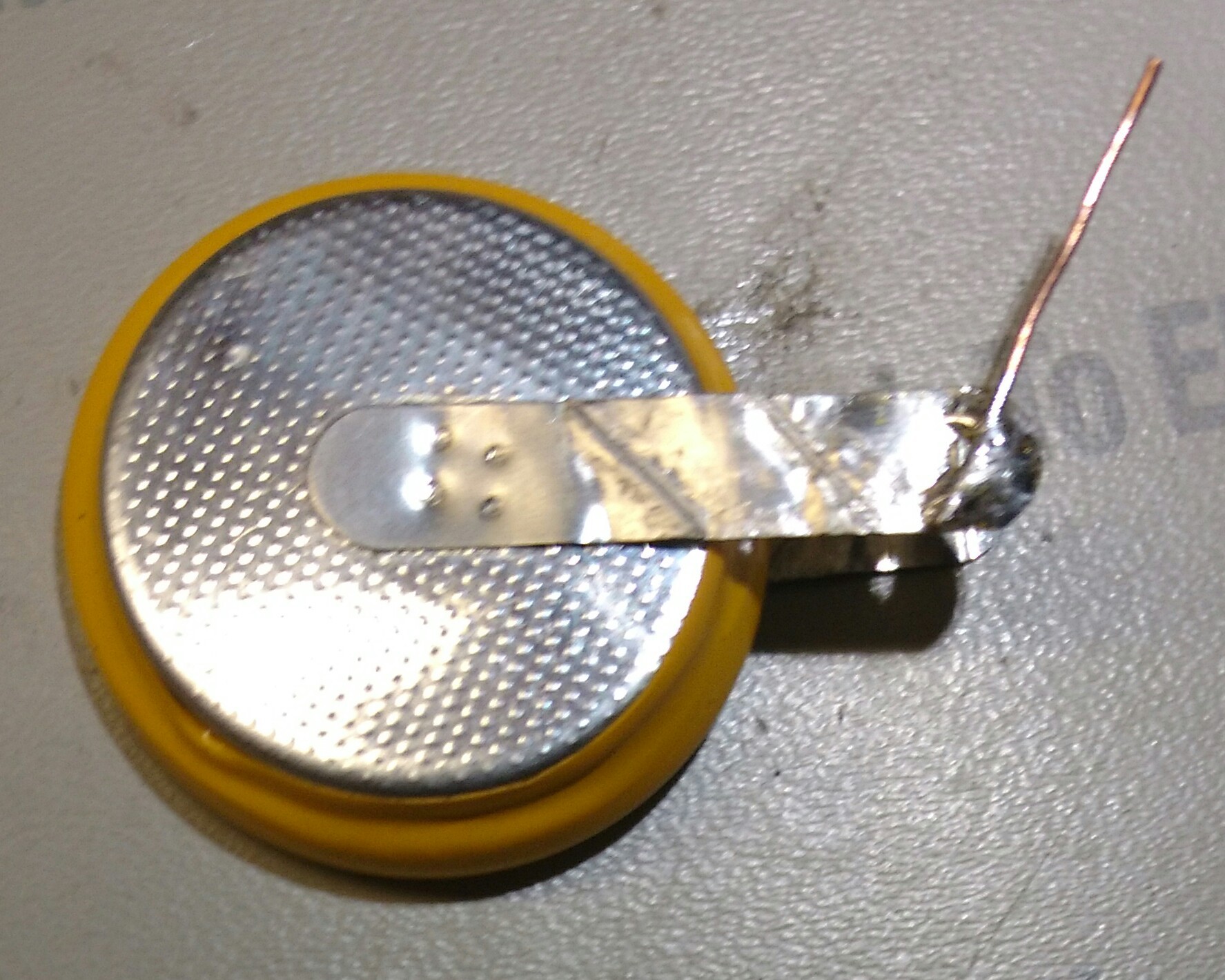
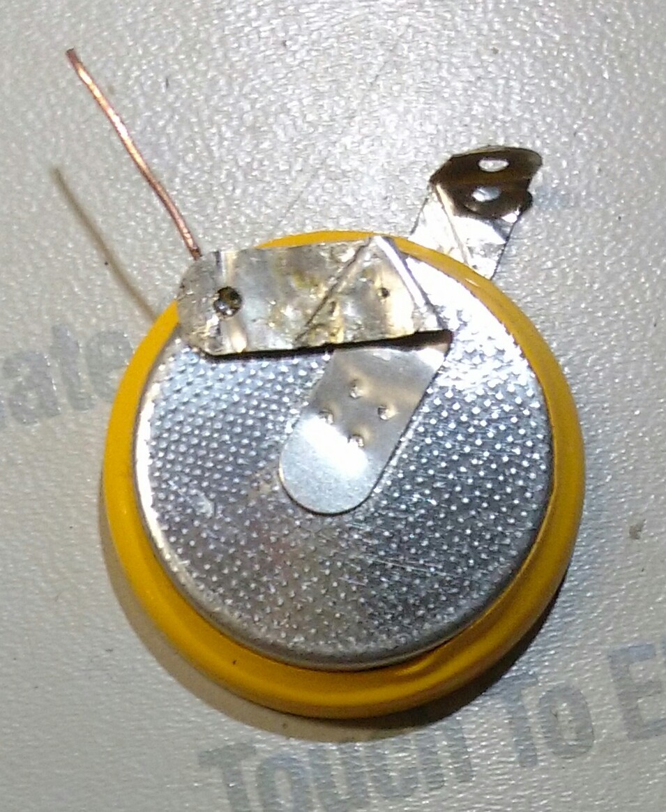
A quick internet search later and I had data for part number LIR2450. It can provide 120mA of current: enough to power a Pi Zero for more than an hour. Since it looks just like a standard coin cell, TECHNICALLY it meets the qualifications of the Coin Cell Challenge! (Note to Benchoff: next time specify the cell chemistry?)

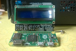
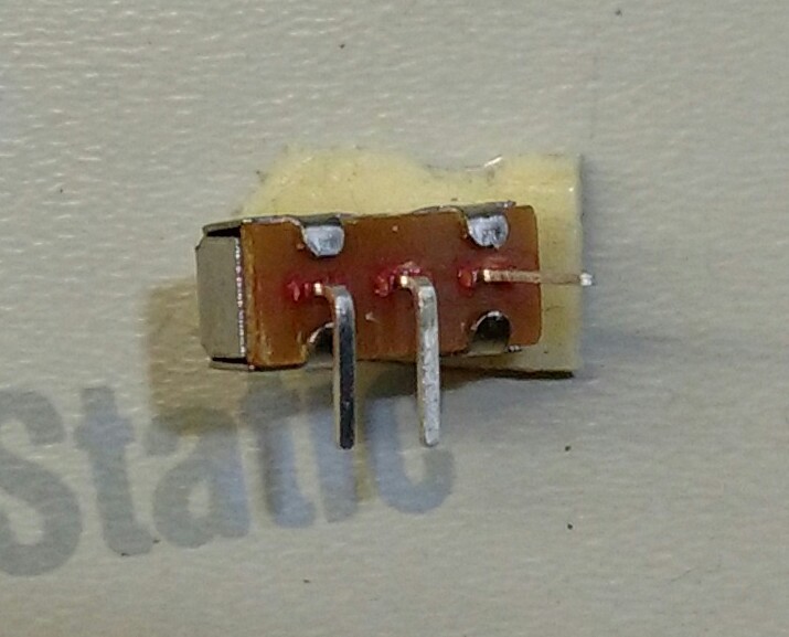
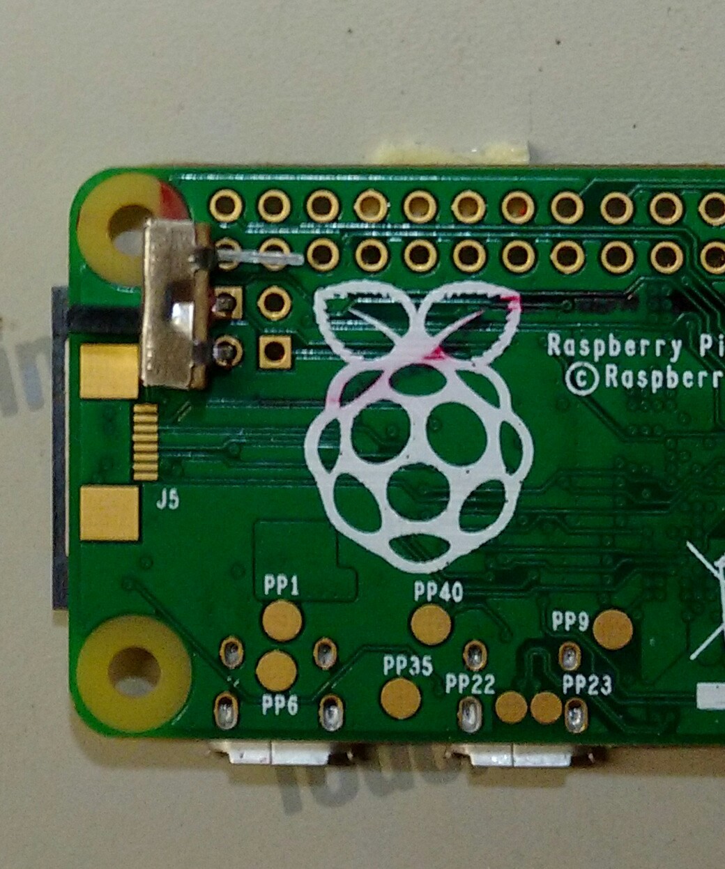
The coin cell and a protection circuit board would fit nicely on the back of the Zero. There's also just enough room for one of those cute little OLED displays, a power switch, and a charging connector. Looks like I have a project!

What can it be used for? An electronic name badge comes to mind. There's even two available holes to attach a lanyard. As for me, I'll be making a tiny Pong game out of mine. Potentiometers will be used for input. If I Velcro the two together their wires would form a lanyard. (And yes, I know this would be better done with a proper microcontroller. But if you have a hammer, everything looks like a nail...)

  • 1 × Pi Zero w/ imaged SD card Get it from the usual sources.
  • 1 × LIR2450 battery with solder tabs I got mine from batteryspace.com ,part LIR2450-V1. Shipping is expensive though.
  • 1 × double sided foam tape Around 1/16" thickness.
  • 1 × bits of wire 30 gauge wire wrap wire is what I used.
  • 1 × 3 pin male header plug with leads Solder wires to a 3-pin header and add heat shrink. Or get creative!

View all 11 components

  • a little problem

    mincepi01/08/2018 at 22:00 0 comments

    The order of the instructions is a little off. Wiring the battery should be directly below preparing the tabs. The editor isn't letting me make this change, so I'll have to re-generate the instructions later.

  • instructions complete

    mincepi01/08/2018 at 21:53 0 comments

    There, I've finished. I promise I'll make the code available for the Pong game once I write it!

  • mostly done

    mincepi01/08/2018 at 20:13 0 comments

    I've mostly finished the instructions. I still need to add pictures of the charging jack and flesh out the instructions for it a bit.

  • initial testing

    mincepi01/05/2018 at 19:30 0 comments

    Parts received, project assembled and tested: it works!

    Next I need to finish the writeup. Then on to writing the kernel module and Pong game.

View all 4 project logs

  • 1
    WARNING:

    ANY PROJECT THAT USES LITHIUM BATTERIES MAY RESULT IN FIRE OR OTHER BAD THINGS. USE THESE INSTRUCTIONS AT YOUR OWN RISK.

  • 2
    INSTALL THE POWER SWITCH AND CHARGING JACK

    Bend the leads on the switch as shown below:

    Solder to the Zero as shown below. Do not solder the unbent lead:

    Below the switch attach the female header plug with foam tape, but don't connect the wires to anything yet.

  • 3
    PREPARE THE BATTERY TABS

    Solder a short wire to the negative battery tab as shown below:

    Bend the battery tabs like this:

View all 8 instructions

Enjoy this project?

Share

Discussions

Similar Projects

Does this project spark your interest?

Become a member to follow this project and never miss any updates