 Rue Mohr
K.C. Lee's comments and some thoughts had me revisit the pwm genorator for two questions.
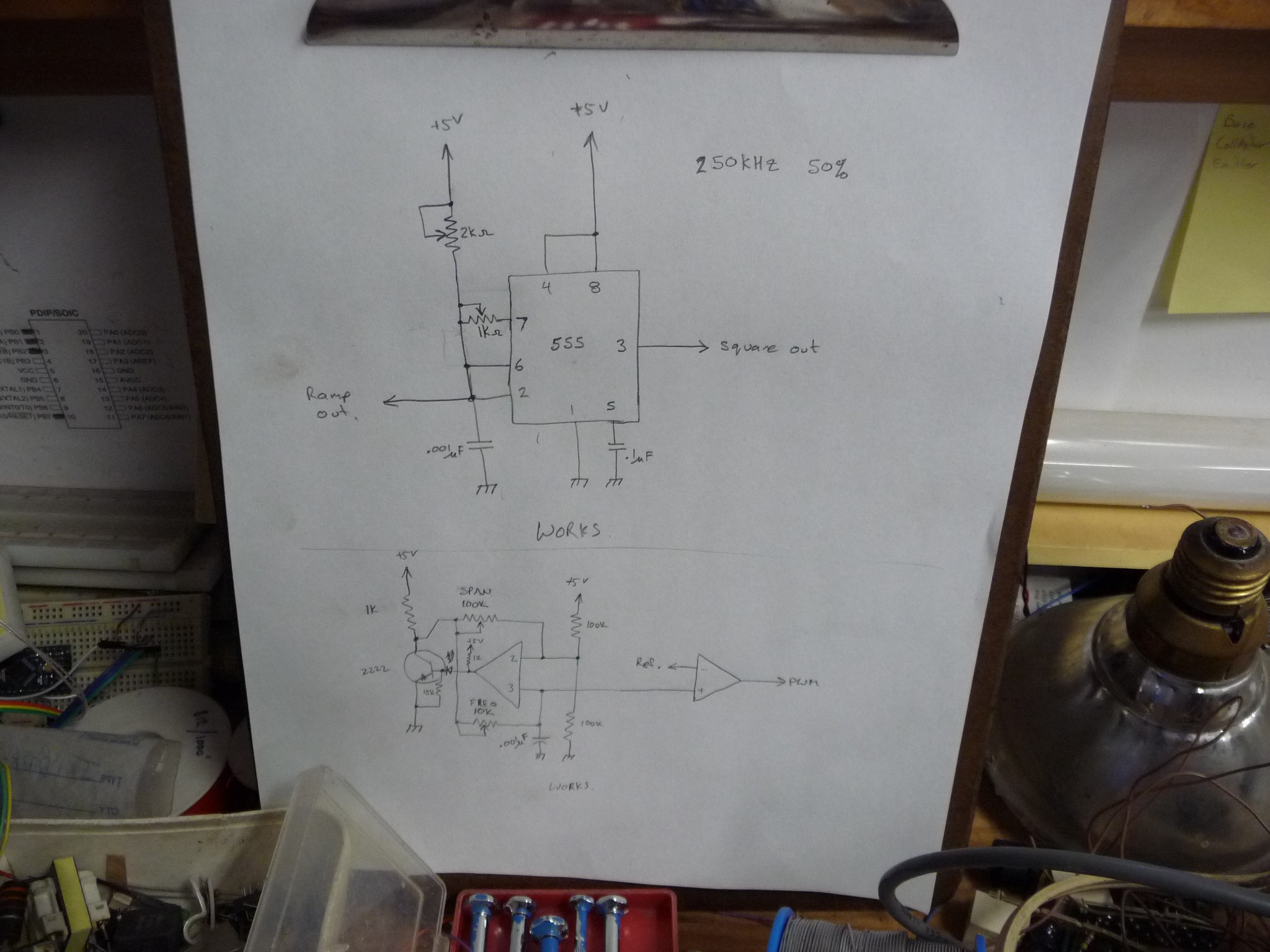
a) Would a 555 make a better ramp generator?
b) Can I get the whole ramp generation circuit to operate on 5V ( that previous design needed to be operated at 12V to get around shortcommings of the LM393 output )
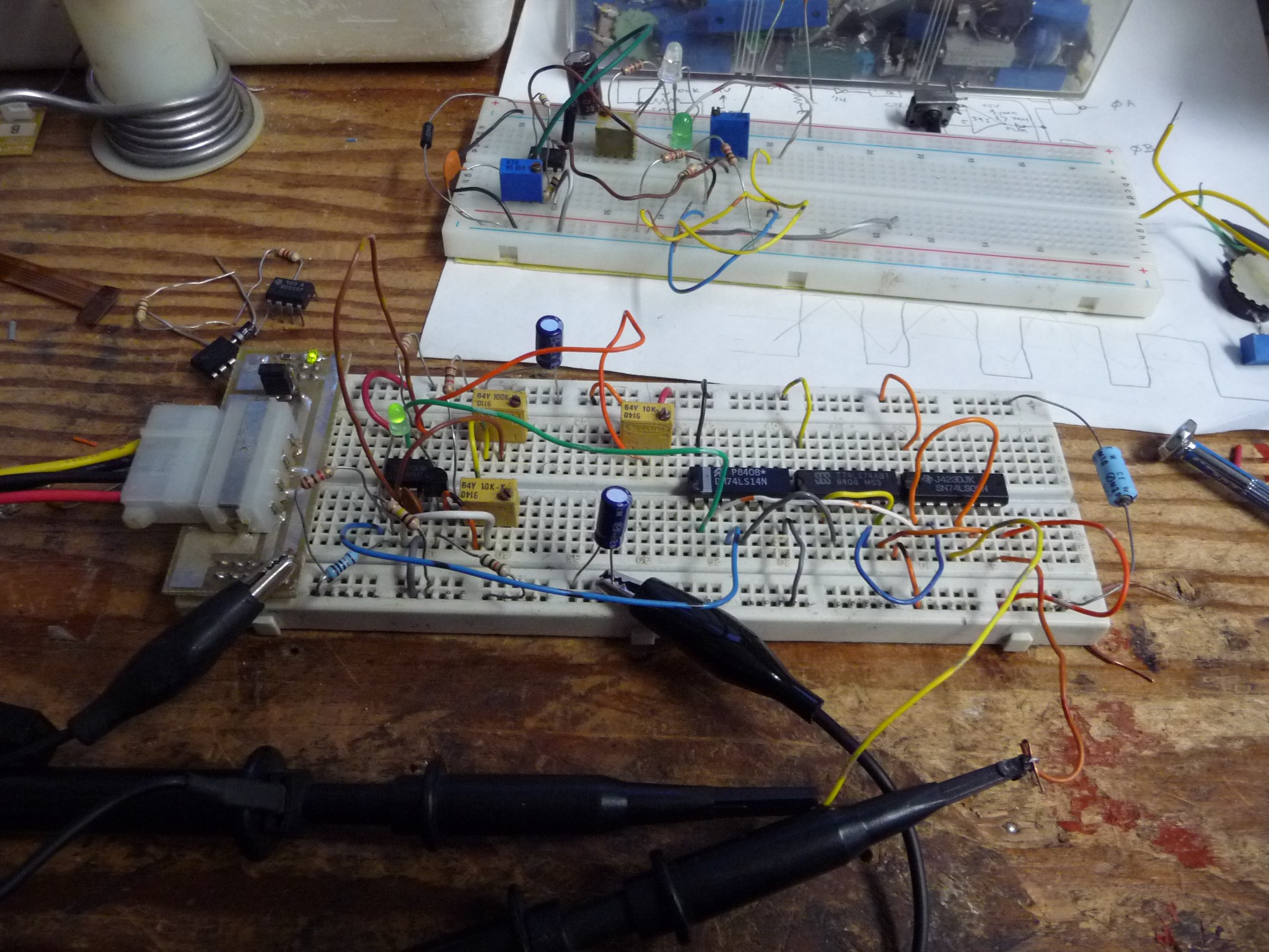
Frist up was the 555, Operated in 50% duty mode. I was able to get it working, and it generated a fine signal. But looking at it on the breadboard I realized that it might not be best for the long term goal. If I use a 555 for a ramp genorator, I still have to use a LM393 for a comparitor to generate the pwm, so far the design also needs a 74xx14 to clean the pwm and synchronization signals, 74xx74 to alternate the phase drive signals, and 74xx00 to gate the pwm to the correct driver side. It would be preferable to not add another chip to the mix, If I can make the LM393 do teh work, its one less chip in the mix. (but it worked)
Next up was trying to adjust the LM393 circuit to operate on just 5V. The output of the LM393 is a common emitter NPN with a current rating of 16mA, To drive a .1uF cap at 250Khz, takes about 70mA. so, I put a PN2222 on the output of it to boost it up. Then I also lowered the bar, by switching to a .001uF timing capacitor. I suppose that means it only needs 0.7mA....
zippo:/files/programming/c# units
You have: .001uF*(3V/4us)
You want: mA
* 0.75
hmm...
zippo:/files/programming/c# ohm -v 5 -i 0.00075
Wattage is: 0.003750
Current is: 0.000750
Voltage is: 5.000000
Resistance is : 6666.666504
hmm.... interesting how these things dont come up while your hacking a circuit on a breadboard...
Anyhow, it worked, and it helps me reduce the chip count of this circuit. Since building it K.C. Lee fired me a schematic of his circuit, and I'd like to use the current source for my LM393
The other mental note is the power filter he used for it, which it a good point, make sure the osc has really clean power.
... I can go to .01uF and still not need the booster transistor...
below are the schematics I tried.
below is the LM393 circuit
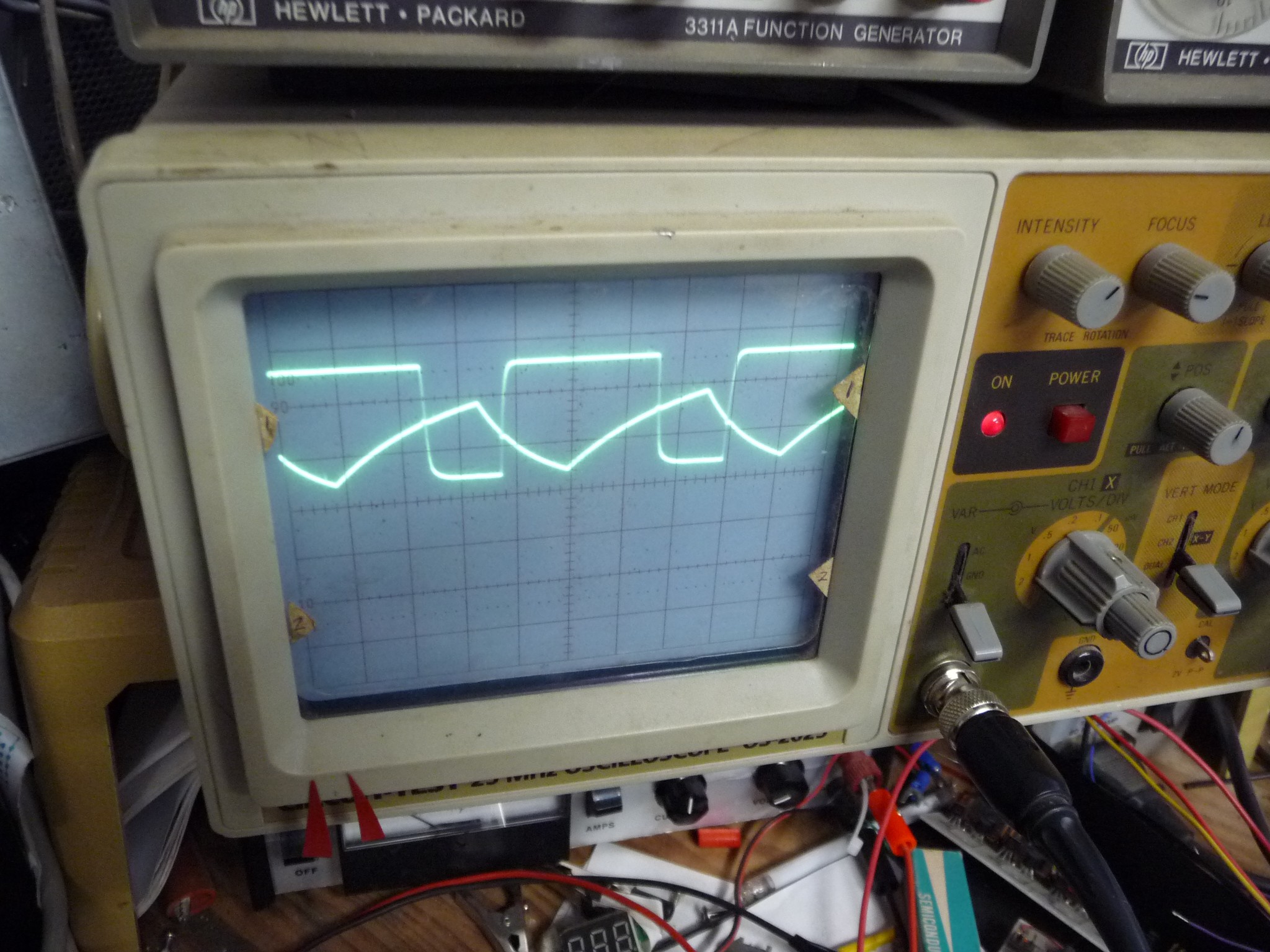
scope traces... (the signal I'm using for generating the pwm is ramped, but all that does it play with the phase of the pwm as the values go up and down)
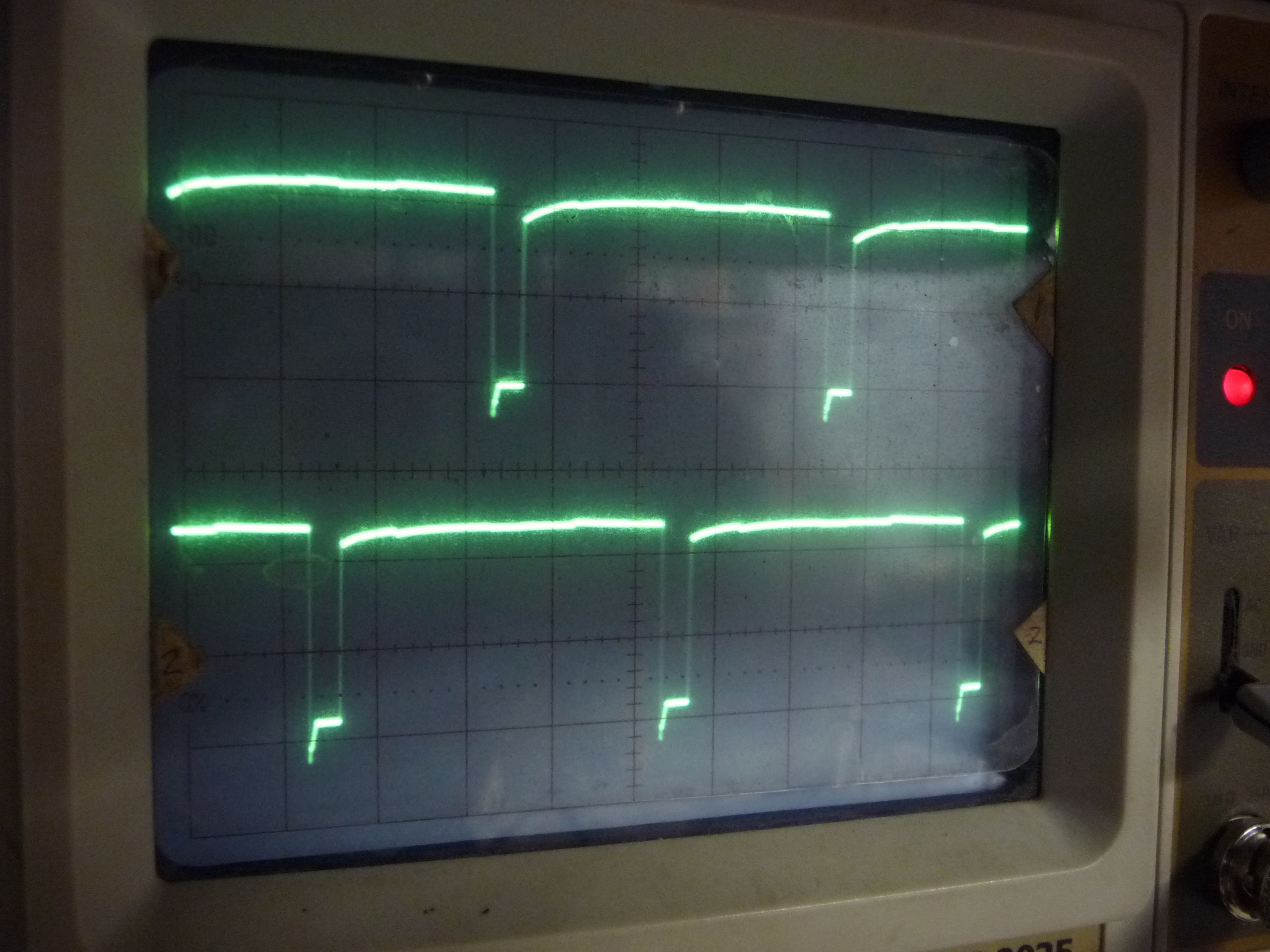
below is the split pwm for sending off to the fet drivers, P channel fets, so low is on. This is the signal out of the 74LS00
Now if you will pardon me I'm gonna take out that transistor and try inserting a current source, ... which just puts a transistor back I suppose... ah well..
Discussions
Become a Hackaday.io Member
Create an account to leave a comment. Already have an account? Log In.