0%
0%
Become a Hackaday.io member
Already have an account? Log in.
Just one more thing
To make the experience fit your profile, pick a username and tell us what interests you.
Pick an awesome username
hackaday.io/
Your profile's URL: hackaday.io/username. Max 25 alphanumeric characters.
Pick a few interests
Projects that share your interests
People that share your interests
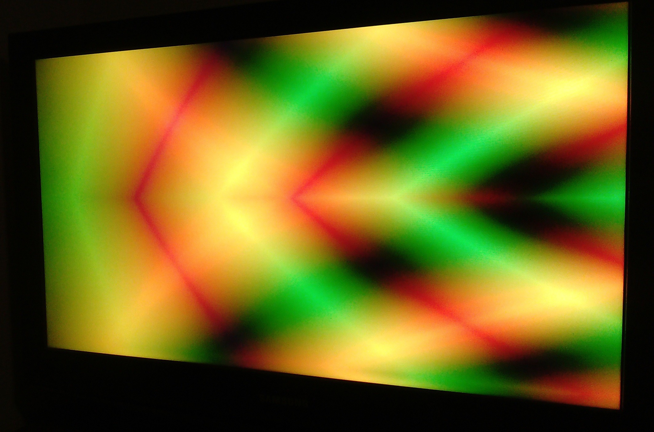
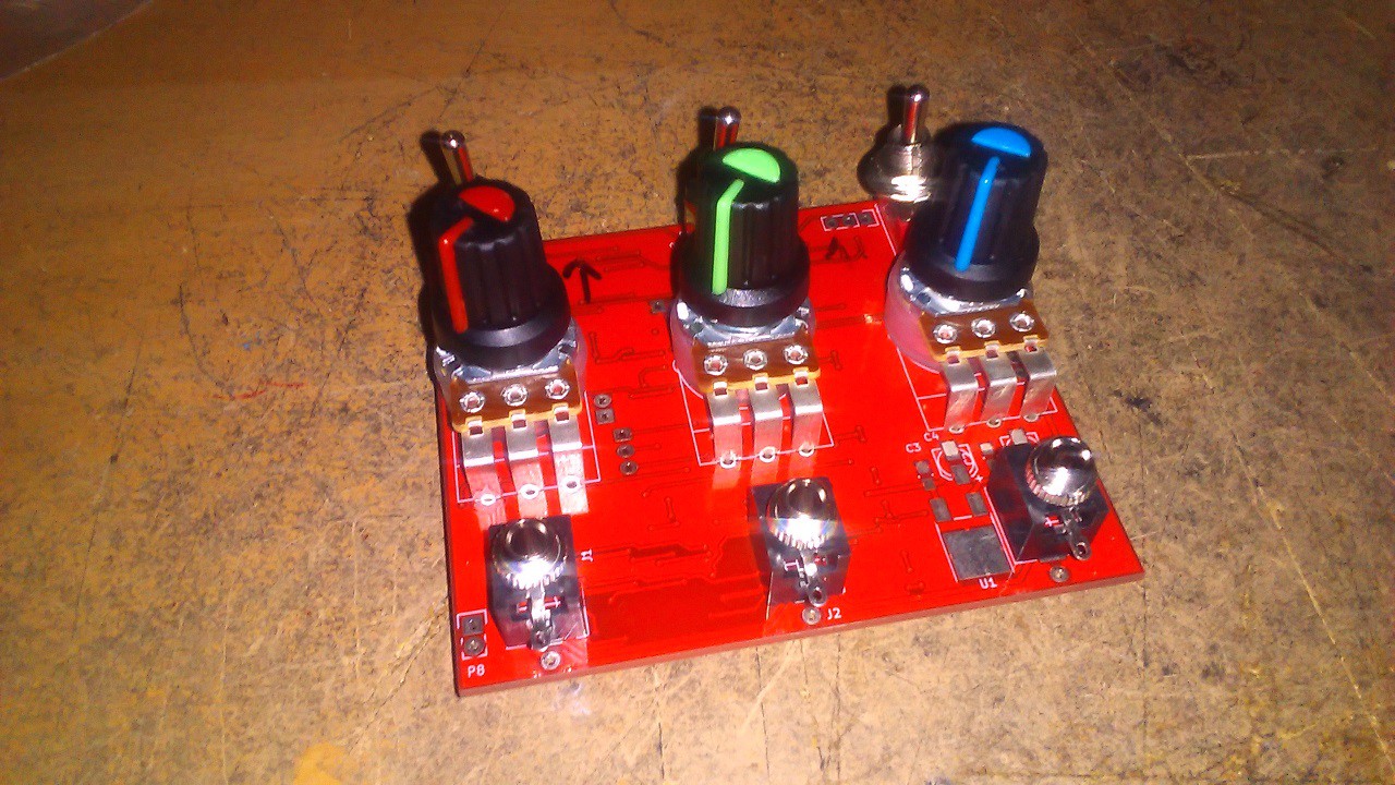
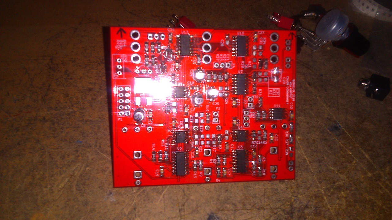
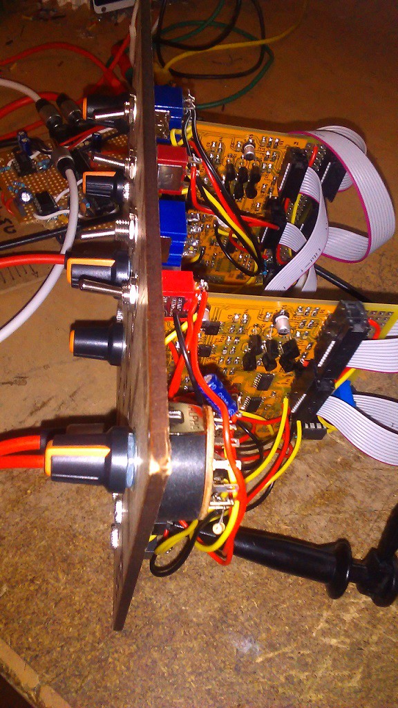
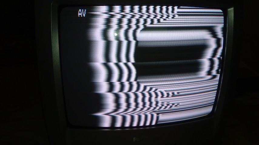
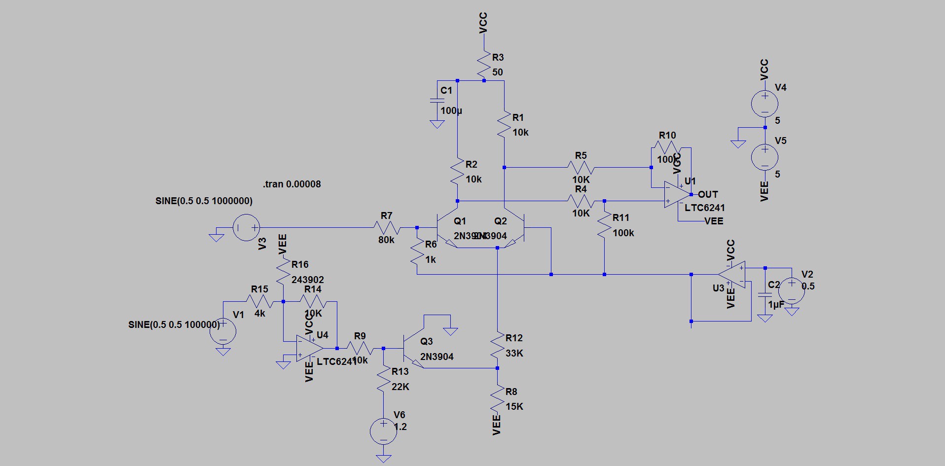
 this board will contain the output color circuit which transforms the 1V signals into the proper 700mV signals needed by the VGA color standard (it seems fine with 1V thought, but the documentation mentions "peak" so I'll play on the safe side). This part will be able to invert the signal as well.


 Gabriel D'Espindula
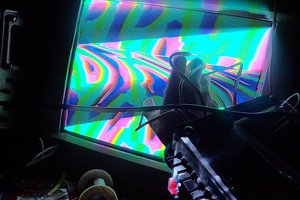
 Russell Kramer
 David Levi
 Sproket
thanks for your interest.
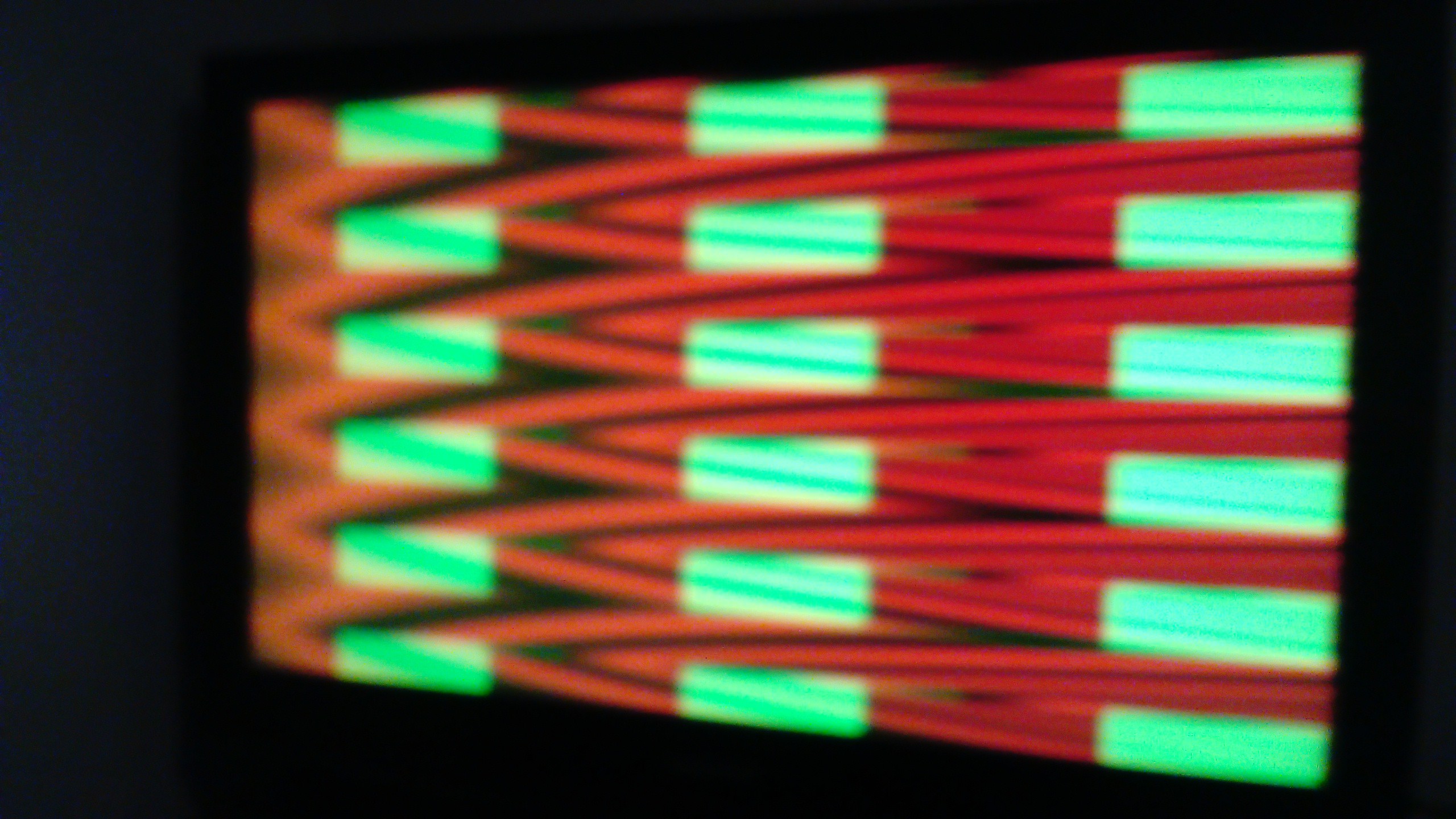
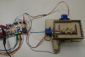
I could do that but I need to find a proper way to capture the video.