 DainBramage
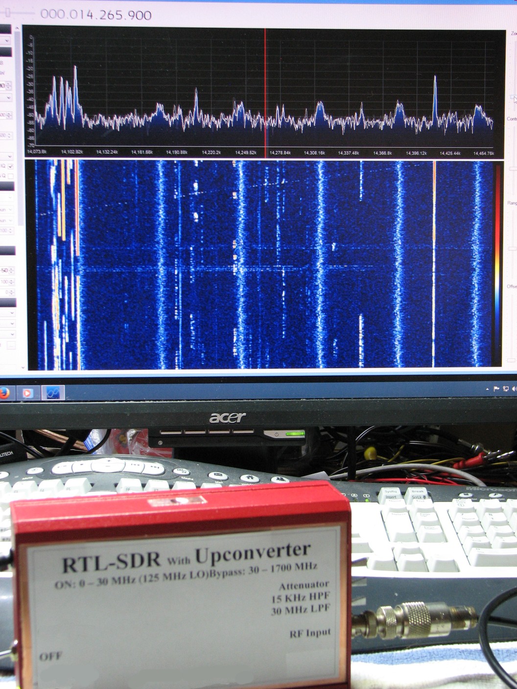
I got my hands on an RTL-SDR a couple of years ago, and was thrilled at the amazing utility of these little devices. A simple $20 device and some free software (along with my desktop computer) gave me some of the functionality of much, much more expensive equipment such as general coverage receivers and spectrum analyzers. As an amateur radio (aka ham) enthusiast, I immediately saw any number of ways that these devices could help me out around the shack. After adding a Ham-It-Up upconverter, I had the ability to observe signals from DC to 1.7 GHz. Not bad for a total investment of $65.
However, I ran into the almost inevitable problem that almost everyone who has used these devices runs into: RFI. Most receivers have filters in place to limit out-of-band interference. An RTL-SDR has no filtering, it is wide open and picks up EVERYTHING.
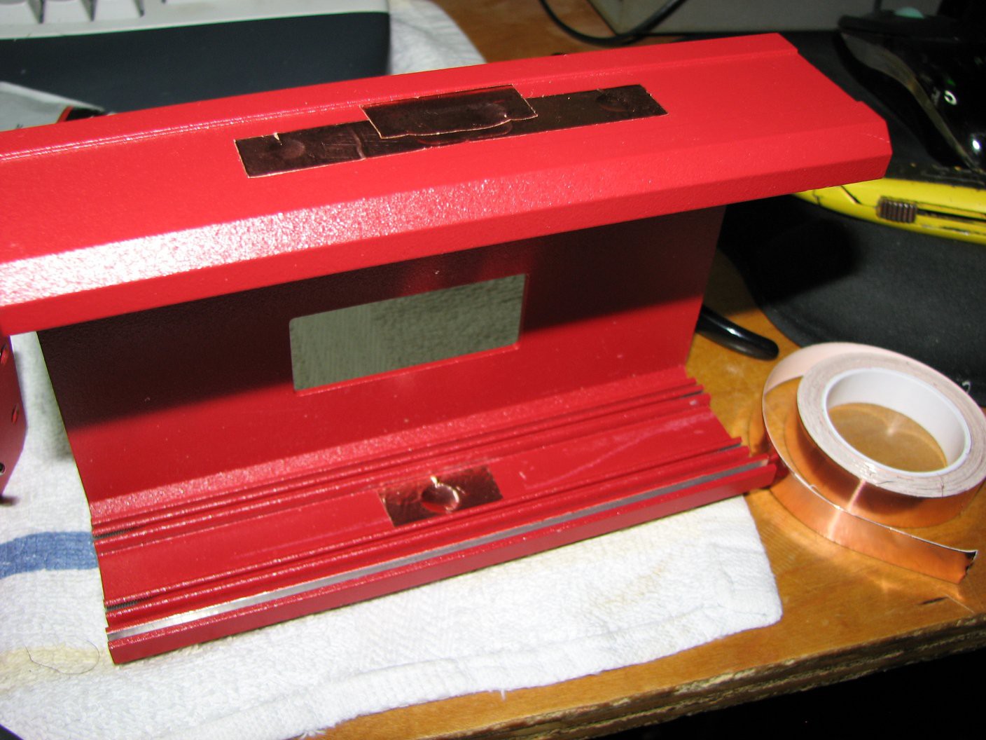
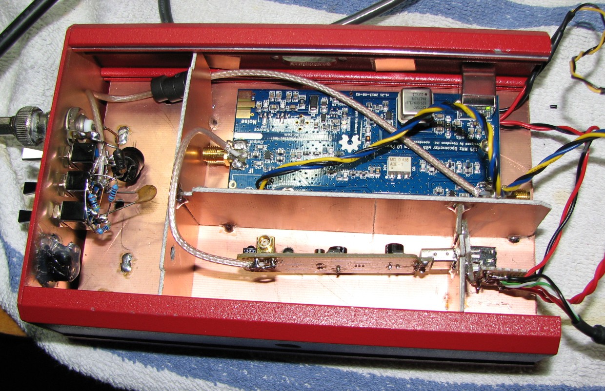
Fortunately, this problem has a very simple solution: shielding. My specific solution comes out of my junque collection: a nice extruded steel case that used to be the home of an industrial thermometer.
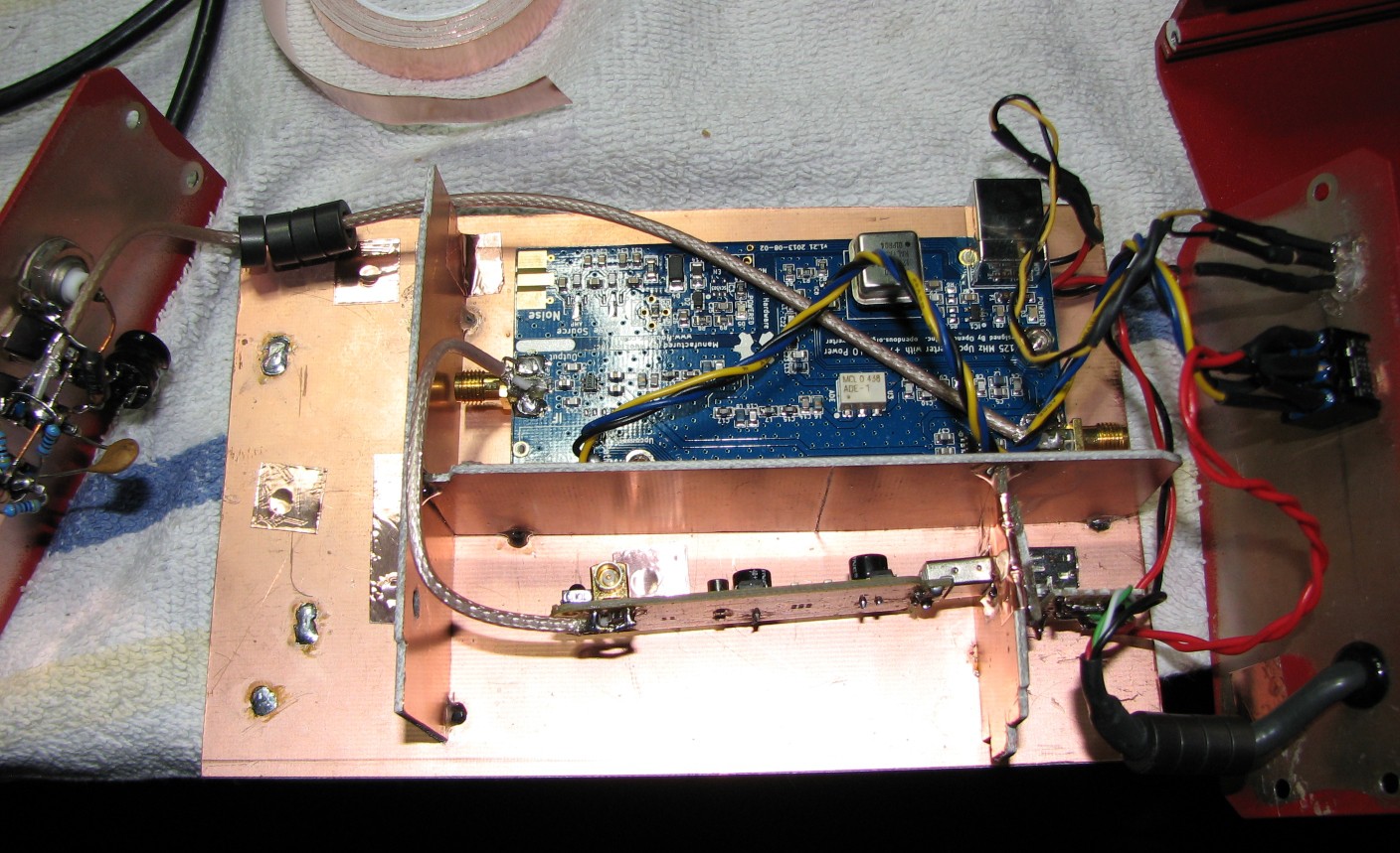
Inside of that case I put some pieces of copper-clad fiberglass in place to support, separate, and shield both the RTL-SDR and the upconverter. I then soldered in some coax to connect the devices to the outside world and each other, added a switch to allow me to switch between modes (upconverter, bypass, and off), and attached a high quality shielded USB cable for data and power. The Junk Box SDR was born.
I also needed something to counter the strong signal coming in from an AM radio station a couple of miles down the road. I decided to add a simple RC filter made of a 100pf cap and a 330 ohm resistor. In theory, this should amount to a 5 MHz high-pass filter. In reality, it does a modest job of reducing interference while still allowing me to listen to the 160 and 80 meter ham bands (1.8 and 3.5 MHz respectively).
Update 11-21-14: The Junk Box SDR has been rebuilt, see project logs below. This is still an ongoing project, as there are still a few ideas I wish to try out with it.
 Work in progress...
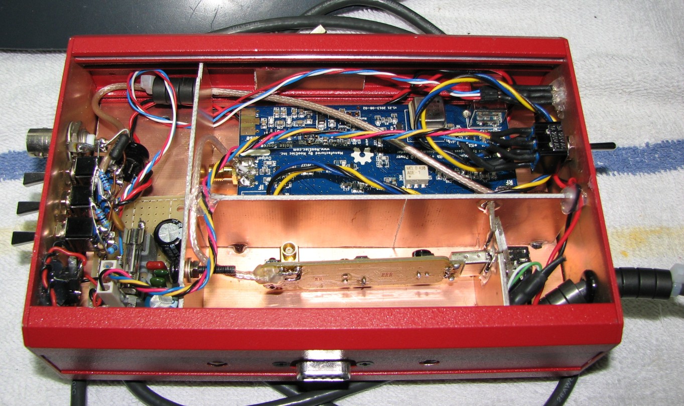


 Lucy Fauth
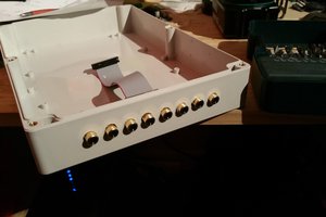
 Matt
Matt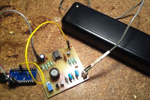
 M.daSilva
 Jarrett
You are on the right-track with shielding, however eliminating EMI and other RF noise requires an OCD-like dedication.
If I may offer some hints:
1. The double-sided PCB shields need a continious solder bead along all seams. (no chinks in the armour ;> )
2. Add an RF-tight fitting lid to the PCB enclosure
3. All wires and cables must be bypassed through the shield walls. No notches or gaps.
4. Coaxial cables must have RF choke beads to eliminate common-mode currents.
5. A better solution might be to separate the individual modules into their own shielded boxes such as cast aluminium from Bud or other OEM
Good luck;
XP