 ronald
Although the original idea was always to sample the steering wheel control resistance line, hacking the JVC Head Unit to the extent that it ended up being hacked was not part of the original idea!
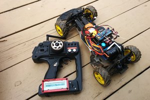
Firstly a Raspberry Pi was trialled (as this would also server as an MP3 Player) but since there are no in built ADCs, a Resistor / Capacitor style "poor man's ADC" was tested. This proved to be highly unreliable and eventually was not going to work for this purpose, so I aborted and moved onto an Arduino based solution instead.
Whilst I was awaiting my Arduino Pro Mini to arrive, I did some research into the JVC Stalk digital control that is present some head units. Since the head unit that was installed did not have the 3.5mm socket in the rear of the unit, I ventured within and found that there was an empty space for where the socket would be in other more expensive models. This looked promising, I could just add the socket and the functionality would just be there right? Hmmm, maybe not. Apart from the missing socket, there were a couple of smd resistors missing and also a couple of links on the main board. OK, so I could put those in and hope for the best but what if the firmware itself didn't contain the required source to even interpret the stalk signals? It felt like too big of a risk to go down that path so I decided to try a direct button hack.
After opening the removable from head unit, it was clear that the firmware really may not have the ability to interpret the stalk signals as there wasn't even an IR Receiver on the front! My research leads me to believe that the stalk and IR signals are the same. Regardless, it was time to see whether the buttons that I wanted to hack were favourable. That is, they were not matrixed with each other, floating high and pulled to ground when pushed. Success! They indeed met all of this criteria, which gave me more confidence that it was all going to work.
Tracing the required buttons, I found that all but the seek button were represented in the socket between the removable head unit and the rest of the radio's body. This meant that only one 'hacky' line needed to be soldered in and wired to the Arduino that would sit in the main radio cavity.
This is where my brother Latino_Aussie steps in. He has far superior soldering skills than I do and quickly attached the seek line to a nearby smd resistor. One of the photos uploaded for this project shows the seek line protruding from the removable head unit. While the iron ran hot, he completed the other lines within the radio body, two of which also required direct coupling to smd resistors.
Back in the land of software, sampling the steering wheel control with the Arduino was accomplished with just a few lines of code, as was driving the JVC digital lines. The only section of source which took a little bit more thought was the rotary encoder. I have published the source on Github (see the links section).
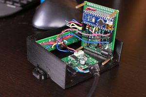
From there on it was just a matter of insulating the Arduino and placing it with an empty cavity on the radio body and putting it all back together again.
There is a YouTube video in the links section showing the completed hack in action.


 atomkemp
 Hardware Unknown
 8teims
Hello,
I am lucky found this project. Currently I am trying to connect wired steering wheel remote to JVC head unit which does not support wired remote. Head unit already hacked, soldered 1 wire for signal SOURCE, SEEK UP and SEEK Down, and 2 wires soldered to rotary encoder for Vol Up and Vol Down signal.
I am totally new to arduino, I bought arduino nano, I use sketch downloaded here and change resistance value as read from A0 pin for each steering button. I connect 2 wires from head unit to arduino pin 5 and 6 directly to control volume up and down. After power up head unit and arduino, push vol button on the steering, no response from head unit. But when I rotate volume on head unit for 1 click then the head unit able to response the steering button. Is there something wrong with my wiring?
Can I get a schematic how to wiring arduino to the head unit?
Thank you
I am sorry for my bad in english..