Close
0%
0%

Neuron Tech

Home Automation and Security

Similar projects worth following
The entire system is comprised of fully autonomous modules capable of operating independently or combining to create one global system. Communication with the system is achieved using wifi and a simple web server allowing for local and remote signalling and control from any wifi enabled device...


The Basics

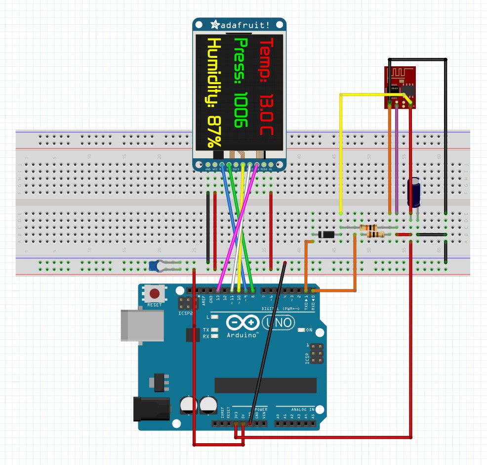
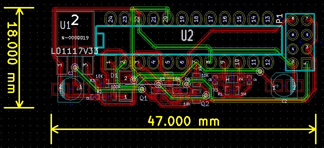
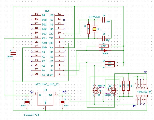
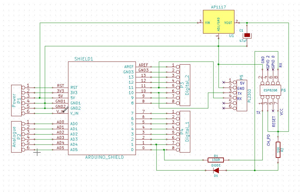
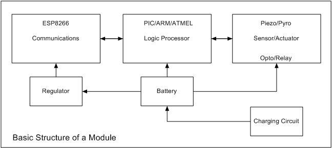
The basic building block (device) for the Home Automation & Security system are electronic modules comprising identical communication and logic circuits and various sensors / actuators...

Registering a Module

On power up, modules first build a list of other active module recording their ID, type and signal strength. They then try to contact the main controller module to register their presence, type and status...

Extending communication

If a newly activated module fails to make contact with the main controller, it will request another module relays its request starting with the module having the highest signal strength and looping through the list until successful...

if successful, they will register the ID of the successful relay module for later use, however, if unsuccessful, they will switch to autonomous mode.

Autonomous

Modules operating autonomously can still communicate with other available module, for example, should a module want to trigger an alarm event and has a record of an Sounder Module in its list of available module, it will send the activation to that Sounder Module thereby conserving its battery by not using it's own sounder...

The right Module for the Job

Although alarm sensor modules have a built in sounder, it is only intended as a fall back device as it would greatly reduce the module batter life... A far better solution would be to signal an available Sounder Module as they are normally connected to the main or have a heavier duty battery...

Modules operating autonomously will also try to contact the main control module on a regular basis...

Mike

  • 1 × ESP 8266 WiFi module

  • Building a server to monitor devices

    Michael O'Toole08/13/2015 at 17:01 0 comments

    I've started another project with details the building of a local server to monitor transmissions from ESP8266 devices... https://hackaday.io/project/7186-esp-8266-web-server

  • Project Update

    Michael O'Toole05/01/2015 at 19:58 0 comments

    When this project was started little was know about the ESP8266 device but its potential was apparent. More recently, several tools to assist in development have been gaining in popularity, including, but are not limited to;

    • LUA (an interpretor language approach)...
    • The very popular and extremely well supported Arduino IDE (can now compile and upload directly to the ESP8266) ...
    • And one or two standalone applications are also actively being developed...

    I don't particularly like interpretive approach used by LUA and while it has some benefits, I much prefer the standard compile, upload and test approach. So, have opted to develop for the ESP8266 using the Arduino IDE...

    I should mention that existing Arduino code and libraries can be used to code for the ESP and what can't currently be use will no doubt be updated...


    This project is reliant on my other ESP projects, so don't expect too much movement until my test & development board is complete (or I find one I don't have to build myself)... Of course, as all projects are related, development on one benefits the others...


  • Work In Progress

    Michael O'Toole11/16/2014 at 17:16 0 comments

    Small delay until I complete another related project to build an ESP8266 development board (https://hackaday.io/project/3352-esp8266-development-pcbs) that will allow me to program the ESP8266... The new development board also allows for testing devices while walking around as their portable...

    In the mean time I'm writing some code and designing some more sensor modules including a WiFi Sounder (the actual alarm part @ ~95db). Also working on the piezo sensor and trying to achieve the results of my early work...

    Mike

  • Little 1.8" TFT for Debug

    Michael O'Toole11/01/2014 at 03:50 0 comments

    Created a version with a small TFT to replace the console for reports... The image is from Fritzen (had to create the ESP8266 component for it, if anyone wants it)...

    I've used zeflo's code (http://zeflo.com/2014/esp8266-weather-display/)... I changed #define dc to 8 and #define rts to 9 as the Adafruit example code use these...

    The little TFT makes a very useful tool... I can plug it in to any of the modules to see the state of play...

    ...

  • Prototype Mk1 PCB

    Michael O'Toole10/27/2014 at 02:01 0 comments

    Although still using full size Micro, I thought I build up a prototype board...

    And schematic....

    The final PCB size could be as small as 13mm high, 15-20mm wide by 30-40mm long, assuming a 3 volt cell or small rechargeable....

    Will add header to allow plugging in of the 1.8" TFT Debug Module,,,

  • Arduino ESP8266 Test Shield

    Michael O'Toole10/24/2014 at 18:20 1 comment

    I've made an Arduino Shield for testing.... here's the schematic... (note, I have replaced original post schematic with this simplified version using all thought-hole components)... The PCB layout below is also updated...

    And a very quick PCB Layout...

    The original post used 2 BSS138's for level shifting but I may have transposed the TX/RX pins of the ESP8266. This newer layout/schema is what I actually use and has been tested for several months with various ESP's...

    Note that the ESP8266 is not suppose to be 5 volt tolerant however, I have tested many and all appear to work perfectly when connected directly to ATMega... If your sketch changes digital pin 0 (RX) to an output, you will need to add level shifting to prevent potential damage to the ESP...

    Mike

  • ESP8266 & Arduino Test Setup

    Michael O'Toole10/17/2014 at 12:30 1 comment

    Test setup (PL2303, ESP 8266 and Arduino Uno)

    Module Baud Rate Notes:

    Various ESP8266 module appears to arrive with baud rate set to 115200 or 57600 while the latest version may actually be set to 9600.... Mine was set to 115200...

    Module Pin Connections:

    Logically chip select (CH_PD) must be held hight for the device to operate... No mention is made in the datasheet for any requirement for RESET, GPIO0 or GPIO2 in the test scenario... It should follow that these pins can be left floating as the manual appears to indicate....

    Please note, several sites insist that one or more of these pins must be connected to supply (3.3 volts) for the device to function... This may depend of the module version but as I said, I only connected CH_PD (chip select) to 3.3 volts from Arduino and left the others floating....

    Level Shifting Note:

    As the module is intended to operates from a 3.3 volts supply, and I communicating with an Arduino (Uno) powered via the USB (5 volts), I will add lever shifting components to avoid blowing the ESP8266 as soon as they arrive....in the mean time, the current simple setup works...

    It took me many hours to get this thing working as I made do with resistors to create a simple level shifter... In principle resistors should have worked but alas they did not... I finally decided to (temporarily) connect direct and voilà....

    Update:

    I have added D1, R1 and R2 to afford some protection and the circuit continues to work... I also noticed if I remove R1, it still works... TX/RX are pulled high internally?

    Mike

  • Made a start...

    Michael O'Toole10/07/2014 at 00:31 0 comments

    Ordered a couple of the ESP8266 to familiarise myself with them, also toying with getting some of the inexpensive transmitters and receivers to see how they perform...

    Working on the program flowcharts has given me a much better idea of what the processor requirements are, so I will continue with this before making any decisions...

    I should point out I have not worked with electronics for some fifteen years since my eyesight started to deteriorate so when working with SMD's I now require a telescope... That's all for now except to add, I am hoping for some support and guidance from the hackaday community...

    I am following all discussions (I can find) relating to the EPS8266... Things are a little confusing at the minute but progress is being made...

    Here's the basic structure of a module...

    14th October.. Parts arrived today so now for some testing... (their tiny, I need new glasses)...

View all 8 project logs

Enjoy this project?

Share

Discussions

Michael O'Toole wrote 10/26/2014 at 06:38 point
Thank you... I'll add it now.... Done!
New to the site and I'm still finding my way around ;)

  Are you sure? yes | no

davedarko wrote 10/25/2014 at 22:38 point
you should also add esp8266 to your tags, so this will pop up when being searched for. Good Luck for your project!

  Are you sure? yes | no

Similar Projects

Does this project spark your interest?

Become a member to follow this project and never miss any updates