 Michael O'Toole
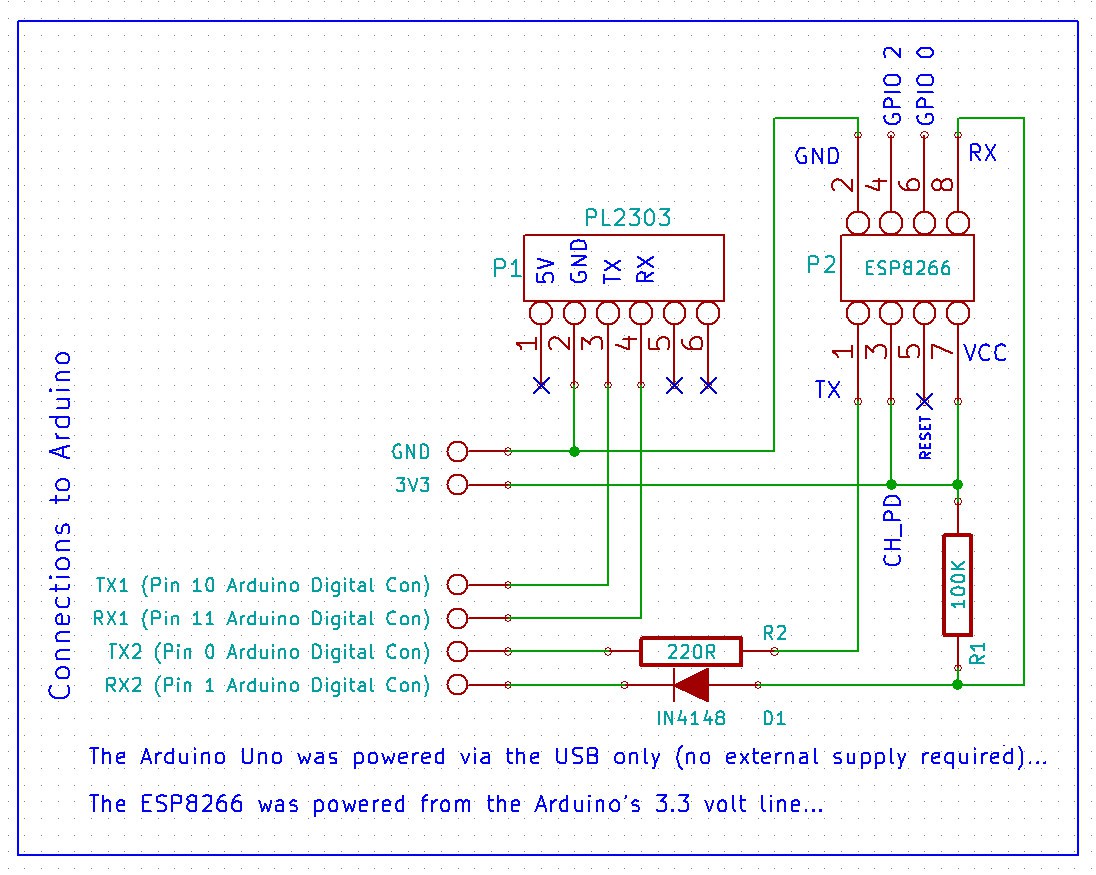
Test setup (PL2303, ESP 8266 and Arduino Uno)
Module Baud Rate Notes:
Various ESP8266 module appears to arrive with baud rate set to 115200 or 57600 while the latest version may actually be set to 9600.... Mine was set to 115200...
Module Pin Connections:
Logically chip select (CH_PD) must be held hight for the device to operate... No mention is made in the datasheet for any requirement for RESET, GPIO0 or GPIO2 in the test scenario... It should follow that these pins can be left floating as the manual appears to indicate....
Please note, several sites insist that one or more of these pins must be connected to supply (3.3 volts) for the device to function... This may depend of the module version but as I said, I only connected CH_PD (chip select) to 3.3 volts from Arduino and left the others floating....
Level Shifting Note:
As the module is intended to operates from a 3.3 volts supply, and I communicating with an Arduino (Uno) powered via the USB (5 volts), I will add lever shifting components to avoid blowing the ESP8266 as soon as they arrive....in the mean time, the current simple setup works...
It took me many hours to get this thing working as I made do with resistors to create a simple level shifter... In principle resistors should have worked but alas they did not... I finally decided to (temporarily) connect direct and voilà....
Update:
I have added D1, R1 and R2 to afford some protection and the circuit continues to work... I also noticed if I remove R1, it still works... TX/RX are pulled high internally?
Mike
Discussions
Become a Hackaday.io Member
Create an account to leave a comment. Already have an account? Log In.
I am curious. Shouldn't the TX pin go to the Arduino's RX pin?
Are you sure? yes | no