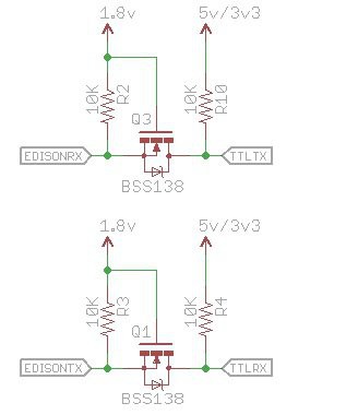
• 1
    Step 1

    The 70pin headers are slightly fiddly to solder on the board but not impossible to do by hand.

    The key to this is a lot of flux.

    Place the board on a flat surface and then using a flux pen, wet the connector area with flux. Then carefully place the connector on the board and line up the pins with the pads on the board.

    Try not to have a soldering iron hotter than 350°C

    Now with a soldering iron, put a tiny amount of solder on the end of the soldering iron (Doesn't matter that the flux in the solder burns off, the flux on the board will take care of it).

    Touch the soldering iron to one corner of the connector pins to tack it down.

    Then adjust the connector if it has moved and when aligned tack the other corner.

    Now add more flux to the pins.

    Add a little more solder to your soldering iron, doesn't need to be much, just so you get a tear drop worth.

    Then on oneside of the connector, gently place your soldering iron and drag the tip from one corner to the other on one side. You should now have soldered all the pins, Don't worry about bridges, we'll sort those out in a little while.

    Now do the same on the other side.


    Now for the bridges. Clean off you iron, removing any excess solder from the iron. Now drag your iron from one corner to the other, this should have the effect of moving all the bridges to just one end of the connector. Do it a few times if the bridge does not move, and add more flux to help.

    Once the bridge is at one end, clean of your iron tip and then place the tip on the pin and drag outwards, not across as you did earlier. The excess solder should wick onto your soldering iron and leave you with no bridge. It may need a couple of tries.

    If the bridge is being a pain try using some solder braid to remove the bridge.

    Now you can do the other side, using the same method.

    Once all this is done you can do a quick test for shorts by using a multimeter on Continuity mode and put both probes on the 2.54mm connectors adjasent to each other and move along.

  • 2
    Step 2

    Simple UART level converter.

    As I'm sure you are aware, the Edison is 1.8v gpio only so you either need to get a 1.8v TTL USB Cable or you can use a 3.3v or 5v Arduino style TTL USB cable, but it will need a shift level to achieve this.

    So a simple design is to use a couple of Mosfets and resistors and wire a small vero board in the following way.

    You will need two BSS138 and four 10k 0805 Resistors, a small piece of vero or strip board or you could use the prototyping area on the breakout board.

    On the vero board cut the copper around the two purple highlighted lines. Then solder on the two Mosfet with the pins as indicated. So the pin on the single side needs to go on one of the cut sidie of the strips as indicated in yellow while the left pins are connected to the shared 1.8v center strip.

    Then put a 10k resistor between the 5v/3v3 like and the single pin (next to the red arrows) and another one for the 1.8v lines (next to the green arrows).

    Now put in a 4pin strip of header pins in the bottom 4 holes and 3 pin strip with the middle pin pulled out on the top.

    Now you can plug in the RX and TX of the TTL as well as the 5v to the red parts.

    Plug in the 1.8v line (pin 2 top) and pin 9 (bottom) and 7 (top) to the board. And you should be good to go.

    Make sure you check all voltages and correct and that there is no 5v comming out the green arrows.