 icstation
Step 1: Function
1) When the starting-up system initializes, the infrared correlation sensor stays in an inactive state, while the system is in a suspensive state.
2) Press key 1 to turn on the infrared correlation sensor, the system begins to work at this time that it records the times that object passes the inducing field of the sensor.(Press key 1 again to paause recording.)
3) Press key 2 to reset number that has been recorded.
Step 2: Material List
1. 1 x ICStation ATMEGA2560 Mega2560 R3 Board Compatible Arduino
2. 1 x 830 Point Solderless PCB Bread Board MB-102 Test DIY
3. 1 x Correlation Photoelectric Infrared Count Sensor Module
4. 39 x 65pcs Breadboard Plug Wire Cable Tire
5. 2 x 12X12X5mm Tact Switches 4 Legs
6. 2 x 100pcs 1K ohm 1/4W 1% Accuracy Metal Film Resistor
7. 1 x +5VDC power supply
8.1 x Common Cathode 4bit Digital Tube 0.36in. Red LED
Step 3: Schematic Diagram
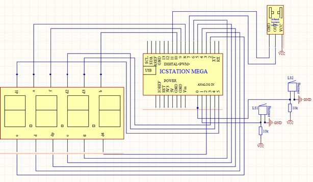
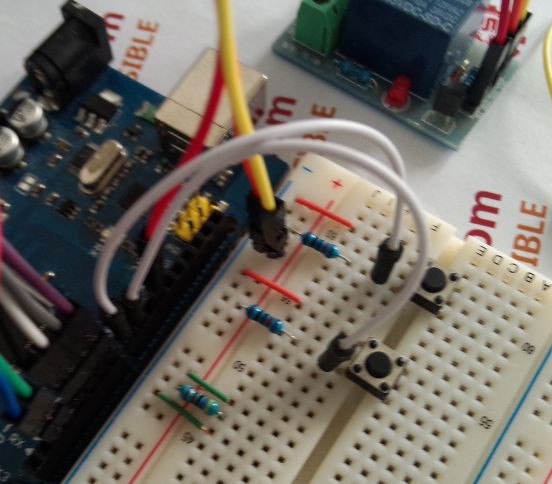
Step 4: Lead to the power supply line and GNDFrom the ICSTATION MEGA , plug +5V power supply and GND to the bread board.And the red bread wire is for supply line, while the black one is GND line.
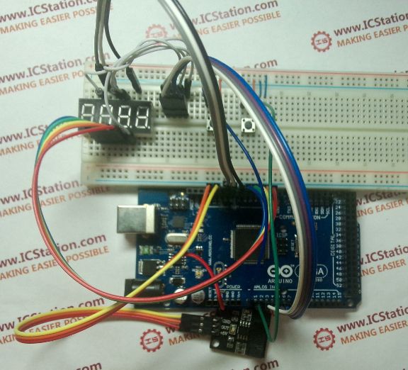
Step 5: The connection of the 4bit digetal tube
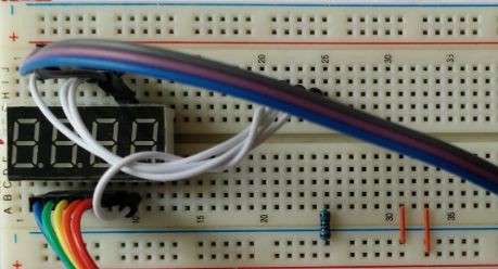
(1) Plug the 4bit Digital Tube into the bread board, and use the DuPont wire to draw forth the digital tube pin.
(2) According to the schematic diagram, connect the pins of 4bit Digital Tube with the pins of ICSTATION MEGA
Step 6: The connection of keys
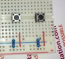
Plug the keys into icstation board. (Connect key 1 to pin A0, key 2 to pin A1)
Step 7: The connection of infrared correlation sensor module
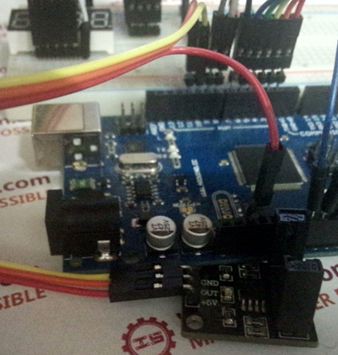
Connect infrared correlation sensor module VCC to icstation board +5V, GND to icstation board pin 11, OUT to pin 12.
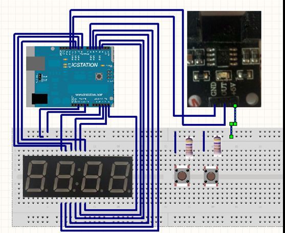
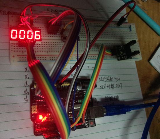
Step 8: The final diagram
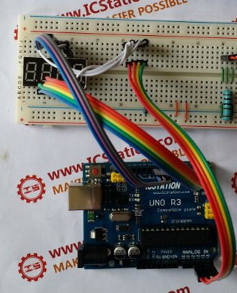
Step 9: The demo figure of the experiment effect
 B K
B K
 Amar Potdar
 DIY GUY Chris