 Greg Duckworth
I intend to create a wiring diagram later in the project so that I can refine and finalise the electronics before I post to help avoid confusion. I have got a working set of electronics to run all 3 axis. This includes a relay to turn the main spindle on and off. In the final version, the spindle will not have digital speed control but its not really necessary without an automatic tool changer.
The box and the reason behind it:
I had been experimenting with the 2 axis version for some time. I am reasonably well organised with the tools but there are loads to keep track of and several projects which use similar sets of fixings and tools. This meant that I spent some time thinking about a case for the electronics and the fixings; like the vice and the toe clamps etc.
The impetus to actually build the enclosure came when I was testing the machinability of some scrap brass when there was an almighty bang and the lights flickered and the blue smoke escaped from my workhorse atx power supply. The supply has served me well for a several years and so I am not annoyed at the life expectancy. This meant that I could not continue to use the mill until the new PSU showed up. So while I was waiting for the PSU, I used my time to make the new box.
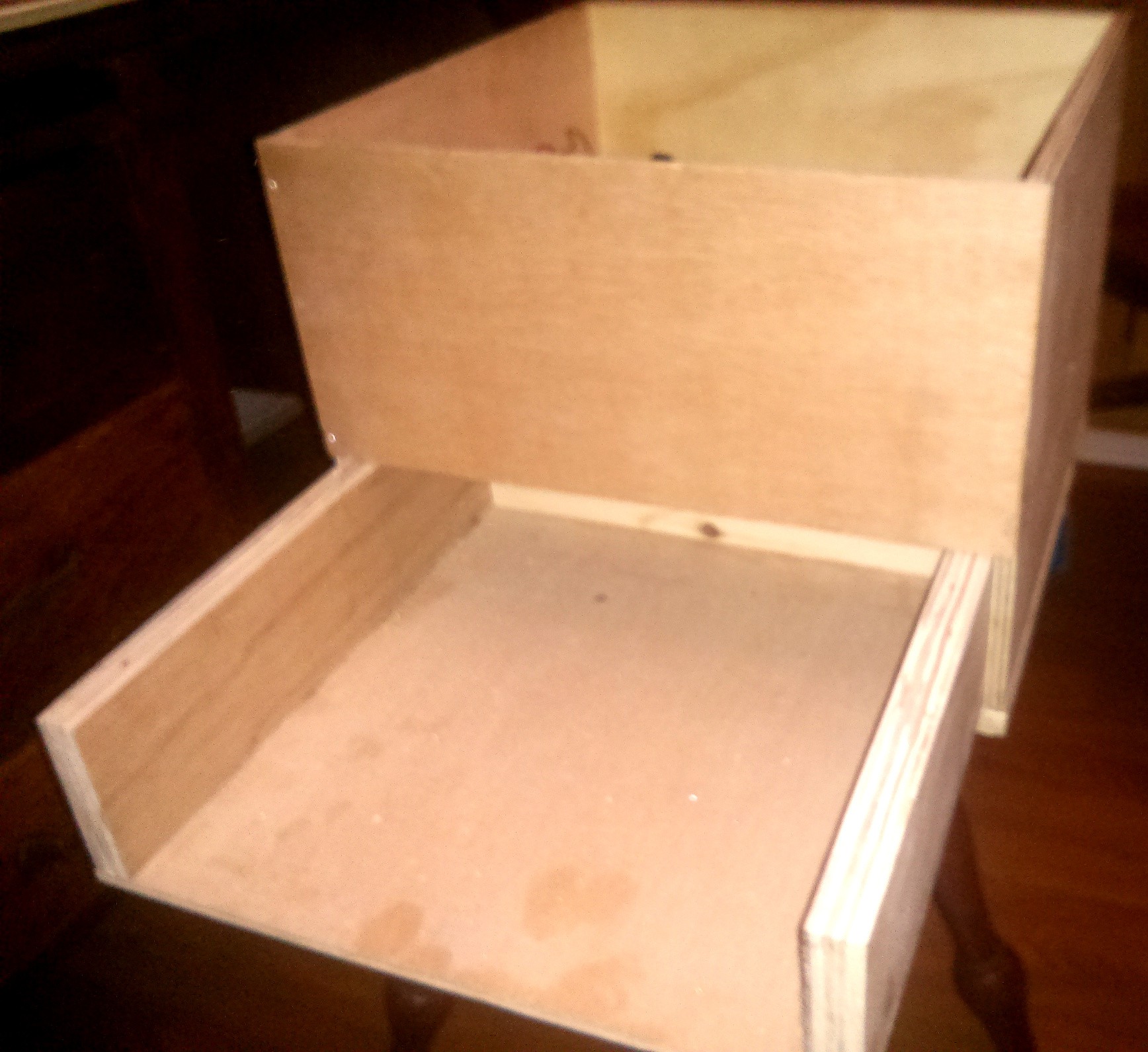
The box was constructed from spare plywood from around the workshop and the dimensions are not really specific other than looking good and leaving enough space to mount all the cable ports and emergency stop button. there is a combination of 18mm ply, 6mm ply and 6mm hardboard. The drawer runs on the plywood base which had to be sanded very smooth to make the drawer run freely. There is a little rail used to support the shelf which the electronics are mounted upon. This shelf is removable in case I ever need to get easier access to the PSU or the control electronics.
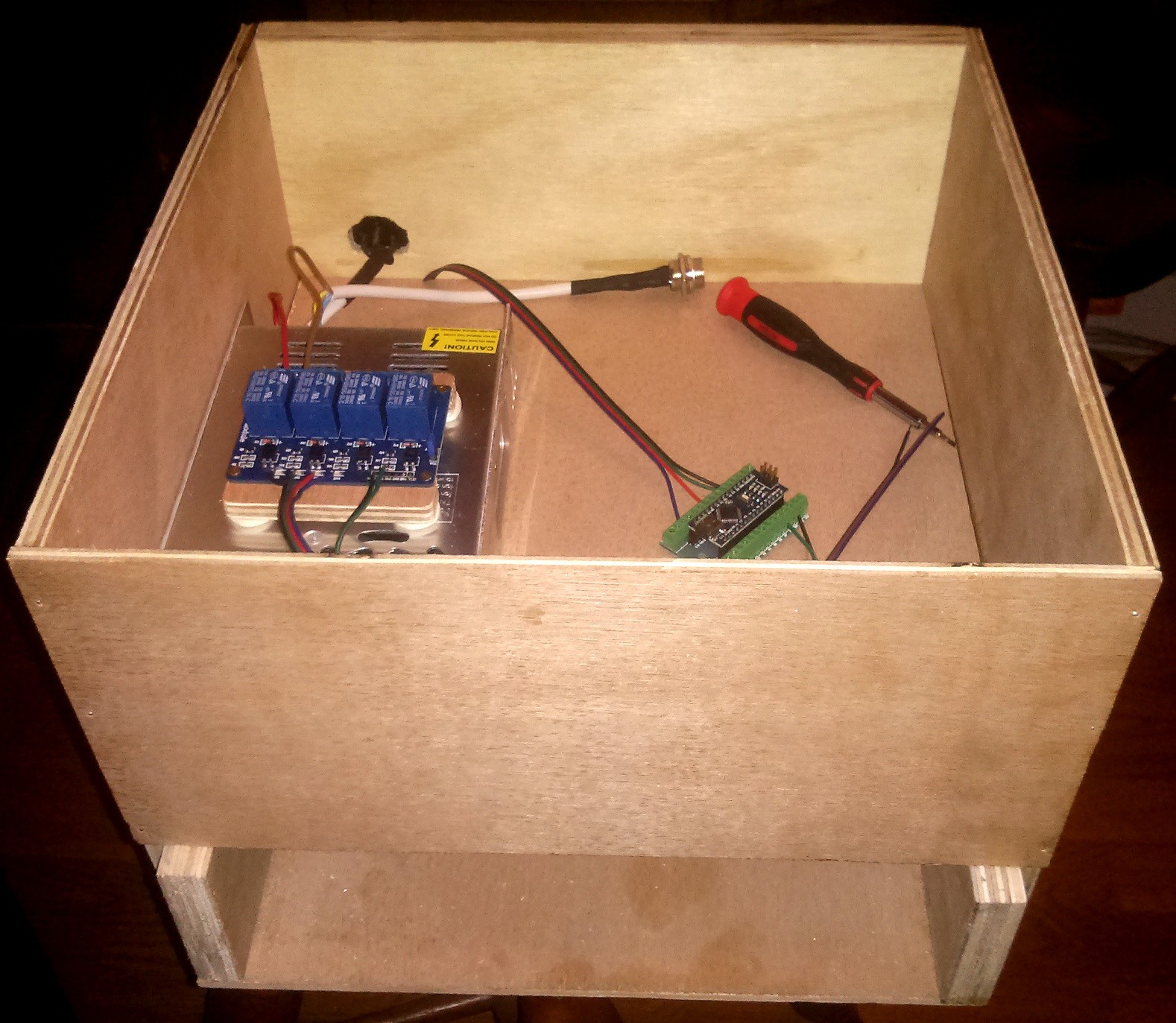
The new 24V 15A PSU mounted on the left with the mains hard wired. As mentioned previously; the current wiring set up is not the one that will be in the final design but it works for the moment. The relay shield and the arduino nano can be seen with some basic wiring. Also I have used a 3 pin aviation connector to allow for relay control for the spindle. The connector is the same type as the 4pin ones used for the stepper motor. I could have used the 4 pin variety but this would allow the steppers to be powered with 240V AC. Not a great option. There are going to be brass plates used to mount the aviations connectors. These were the first things milled when the mill was mounted on the box.
Discussions
Become a Hackaday.io Member
Create an account to leave a comment. Already have an account? Log In.