 Ross Bochnek
10/14/14
Dave figured out that the servo motors only need a minimum of 24VDC, and we're going to use our 30V PSU for testing. Dave has a source for controllers for the motors, and $50 will cover all 4 brushed motors. I think we'll want to control those controllers with a microcontroller, and there are lots of options.
---
10/22/14
There are at least 2 different servos in this bot. Their mutual manufacturer, Yaskawa, is still in business, and I have requested documentation from them about the servos I have identified in the bot so far. They are both brushed, totally enclosed, self-cooling, continuous, DC motors with optical encoders. Their encoders seem to vary in voltage, output waveform, and possibly pulses per revolution.
The servos are:
Minertia Motor Mini Series
UGTMEM-03MC4OE
Optcal Encoder possibly SJ type
close datasheet includes: TSE2-C249-1C.pdf
&
Minertia Motor RM Series
UGRMEM-02SDS21
with
UTOPI-08ZAH Optical Encoder at 800 pulses/revolution
close datasheet includes: TSE-C253-10C.pdf
Most data has so far been found on Yaskawa's own paper data sheets that are probably old, low quality, and have been scanned. In the late 1970's or early 80's, the Seiko robot included motors that probably came after the data sheets were created, judging by their "Design Order" letters C and D in their respective product codes. Hopefully, Yaskawa will find some more updated and higher quality data sheets to send me; even if they have to scan them for the first time.
---
11/5/14
Tonight, Dave uncovered the end effector ("A" Axis) servo...
Aaron or Dave post an image or the codes from the end-effector servo. I've had some luck finding specs on the servos based on their label codes.
---
11/8/14
http://www.ti.com.cn/general/cn/docs/lit/getliterature.tsp?genericPartNumber=sn75183&fileType=pdfThere is a wire wrapped circuit board I removed from the controller. That was one of the ends that the colorful ribbon cable was connected to, but I can't find what the other end went to. The board only has one type of IC left on it: the SN75153N. Judging by the empty IC sockets with different numbers of wired pins, it had 2 other types of ICs. I think some of the board was used to read the optical encoders of the servos. The SN75153N is a quad differential line driver, and my phone insists on pasting the datasheet link only at the top of this post. Might it have been used to read the optical encoders? I'm not yet familiar with differential line drivers.
---
Dave posted:
"
The number of wires going to the encoder will help determine what type it is.
Single Ended usually uses 4 wires. Ground, power, and 2 signal wires.
Differential usually uses 6 wires. Ground, power and 4 signal wires.
Single Ended uses the presence or absence of voltage relative to ground to indicate a high or low state.
Differential uses the relative voltage difference between 2 signal wires to indicate high or low. The wires are not tied to power or ground. They float. They are less sensitive to intereference since stray EMF will affect both wires similarly causing little or no relative voltage difference. You get a higher signal to noise ratio.
Most everything you see now days is 5V or 3.3V single ended. Occasionally 5V or 3.3V differential.
Going back a few (many) years you also see 12V, 15V, and 24V with differential being more widely used than single ended.
20ma current loop was also popular. It is differential but uses current instead of voltage to indicate a high(20ma) or low(4ma) state. You often see current loop used with one side tied to ground (not floating).
The main design advantage to current loop is that you instantly know if a wire comes loose. With digital circuits, an unconnected pin floats high. You have no direct way to tell if you are getting a constant high signal, or if the wire fell off.
DC Brushed motors will use 2 wires for power.
DC Brushless motors will use 3 or more wires for power, sometimes many more.
Stepper motors will use a minimum of 4 wires, and a max of 8 - except for 5-phase ones that will have 5 or 10.
Maybe add 1 to the above numbers if they include a frame ground.
There is no law that says you can't put an encoder on a stepper motor.
"
---
11/9/14
Posting on a phone, and lost a detailed post, so the summary is:
Probably Single Ended, with many ground pins, separate power, and 2 data pins per encoder.
Each servo driver connector has 5 pins: 2 to its own controller card, usually 2 to the I/O card, and a common that's not ground and possibly power.
---
11/26/14
-ALL 4 brushed DC Servo motors test OK in both directions, and confirmed that the mechanics seem OK
-Instead of using the original motherboard, we decided we'll re-mount the Servo Drive connectors onto a perfboard, along with new pins for the Servo Encoders
-Dave says the DC motor controllers will indeed work with brushed servo motors and and logic controller (in our case, an Arduino Mega)
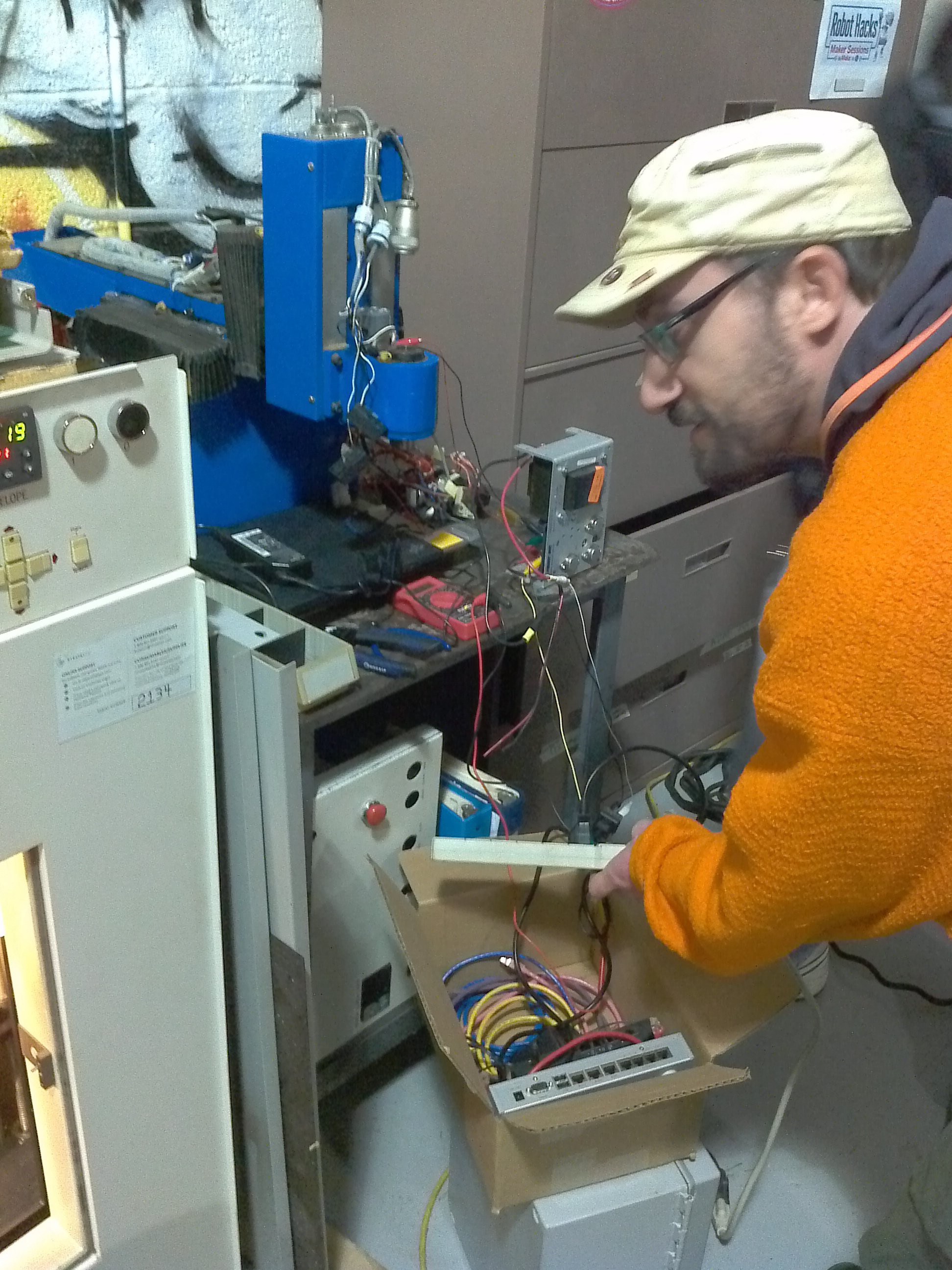 (Above), we tested the A axis (end effector) servo with the PSU we're going to use. Even after pulsing the power, the capacitor kept the servo spinning. (Below), without the end stops connected, we decided to use a variable PSU for the other axes. All 4 servos do indeed work in both directions.
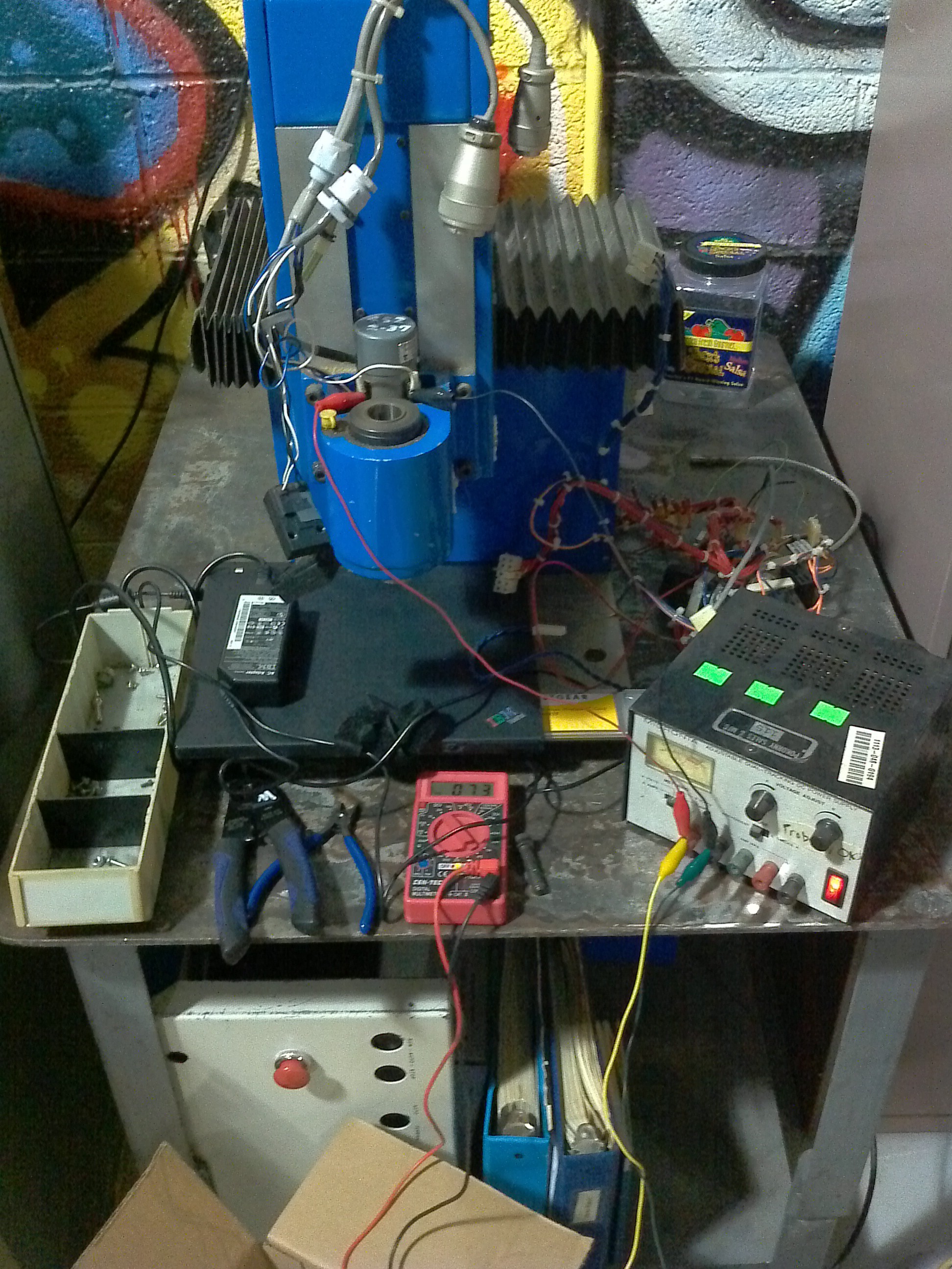
Discussions
Become a Hackaday.io Member
Create an account to leave a comment. Already have an account? Log In.