 Ross Bochnek
11/5/14
With Aaron, we tried to trace the controller cables. I documented the wirewrap job that had been done, probably at Case, as well as the connectors. Then I removed the offending innards and placed them aside, including an obsolete sort of motherboard. Now, we can make our own masterboard to connect the cables that run to/from the robot arm to its new brain and servo controllers. We also plan to cram this all, plus a PSU and a PC motherboard into the existing controller case.
...
I'm calling our new connector board a Masterboard to differentiate it from the PC Motherboard or SBC we're going to also put in that enclosure. Do you think we should identify and shop for the connectors that are on the old connector board, or should we just hot air rework them off the original board to put on the Masterboard? I'd like the Masterboard to have connectors on one or two edges to 1/10"-center IDE ribbon cables or jumper wires, and then most of it, initially could be a huge breadboard. Then, we could replace the breadboard with either a PCB or perfboard that accepts the ribbon cables or jumpers. I can think of a similar way to do it that I won't try to describe here, since I'm sure you'll think of variations. How do you think we should do this kind of wiring so we can both prototype and then move to something more permanent?
---
Old Motherboard:
11/11/14
I've traced out all of the connectors on the original motherboard, and plan to create a schematic.
I also found a diagram of the robot's sensors; mostly limit switches, which improve accuracy and prevent physical damage from over travel.
Let's take a look at the power rectifier board, fuses, switches, and indicators inside the original controller case. The controller originally had 240V AC 3 phase power, and there are so many cut wires that we can either trace them or start fresh with the power. We're using a new PSU anyway.
I have an idea to put the controller inside one of our PLC cases, and mount a computer monitor on the inside of the door.
At our meetup on 11/11/14, we'll continue discussing plans for power, case, board interfacing and stacking, how we're going to protect the robot from itself electrically and physically via fuses/sensors/overcurrent protections/E stops, and what I learned about the connectors this weekend.
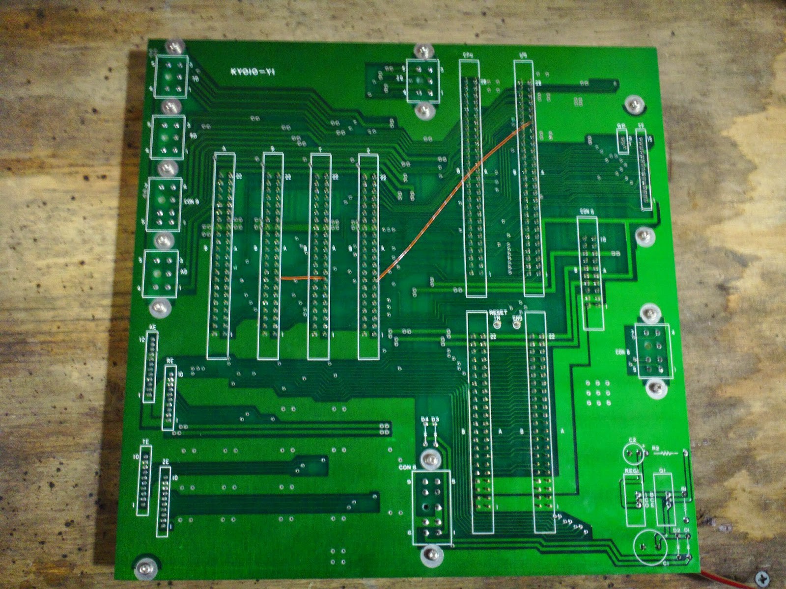
OEM Seiko Robot Controller Motherboard
numbers indicate how many connections to what
there were 4 servo controller boards, 1 CPU board, and 1 I/O board
Axis Z
Encoder Connector
-5 GND
-3 to own servo controller board
-2 unconnected
Driver Connector
-2 to own servo controller board
-1 to I/O board
-1 to GP
-1 unconnected
Axis T
Encoder Connector
-5 GND
-3 to own servo controller board
-2 unconnected
Driver Connector
-2 to own servo controller board
-2 to I/O board
-1 to GP
Axis R
Encoder Connector
-5 GND
-3 to own servo controller board
-1 unconnected
-1 axis R encoder connector
Driver Connector
-2 to own servo controller board
-2 to I/O board
-1 to GP
Axis A
Encoder Connector
-5 GND
-3 to own servo controller board
-1 to servo controller board Axis X
-1 unconnected
-1 axis R encoder connector
-1 to G connector
Driver Connector
-2 to own servo controller board
-2 to I/O board
-1 to GP
Other connectors
GP
-1 to each Driver Connector
-1 to Con G
-1 to Con 8
Con G [Gripper?]
-2 GND
-8 to CPU board
-8 to I/O board
-1 to Axis A Encoder Connector
-2 to each servo controller card
-1 to GP
-3 to Con 9
-unconnected
Con 6
-3 GND
-1 to a capacitor
-2 to a diode
-2 to Con G
-1 to itself
-1 to Axis A Encoder Connector
-2 to CPU board
-2 to I/O board
-1 to each servo controller board
Con 8
-5 to I/O board
-1 to GP
-1 unconnected
Con 9
-2 to each servo controller board (8 total connections: 4 individual pins to each + 1 pins to all 4)
-1 to Con 9
-2 to Con G
-1 to its own pin (that connects to all 4 servo controller boards)
Con SE
-4 GND
-8 to I/O board
-3 unconnected
=====
11/18/14
- Motherboard Hacking: move servo Drive and Encoder connectors/breakouts to chosen PLC enclosure, cut out panel mounts for cable connectors, solder wires to original motherboard connector pins on the back, so we can use these as both jumper wires to a big breadboard and eventually a shield for the Arduino Mega, connect breakout to original motherboard and mount it upside down on standoffs
---
11/22/14
Today, I:
-removed a 28v or 24v power supplies from 2nd case, in preparation for moving it to 1st case. I then put 2nd case back in the We Lab.
-removed extraneous stuff from the 1st case, which will house the hacked controller
-traced unknown connectors to parts wired to them; mostly power, sensor, and gripper related
-removed potentially reusable parts from the stock controller case and put the case on the shelf below the robot. Reusable parts include the switches, and panel connectors with their breakout connections
-after measuring the servo and encoder board connector's pin spacing, and finding them at multiples of 1/10" centers, I reconsidered desoldering the connections to put them on a perfboard. I still want to look at my pinouts to determine if there might be a real benefit to keeping them on the original motherboard
-removed some wires from their terminal bus strips
---
11/26/14
We had a powerful hack session tonight.
-24 VDC PSU tested OK
-28 VDC PSU tested OK
-ALL 4 brushed DC Servo motors test OK in both directions, and confirmed that the mechanics seem OK
-Instead of using the original motherboard, we decided we'll re-mount the Servo Drive connectors onto a perfboard, along with new pins for the Servo Encoders
-Removed all components from the PLC case we're using, due to the extraneous components being mounted on a panel that had to be removed to unbolt those components. We'll continue to strip the panel of extraneous components, and maybe replace it. Much of the future work will be done on this or a replacement panel before mounting it back in.
-Dave says the DC motor controllers will indeed work with brushed servo motors and and logic controller (in our case, an Arduino Mega)
QUESTION:
-Since the panel is metal, it's both hard to drill through and since it's conductive, could create shorts if 2 contacts touch it. But, it's also fireproof and dissipates heat well. Should we switch to a panel that is easier to mount screws to, drill bolt holes into, insulating, but may not be as fireproof or dissipate heat as well? If so, we could still add heatsinks, fans, and mount components that need heat dissipation to the metal enclosure that the panel will drop into. Shall we try something like a plastic or wood board? It should be something that doesn't build up static electricity either. If we stuck with metal, we'd probably have to stick to using bolts, but to prevent having to remove the panel to remove anything, we'd probably want to at least attach one side of the panel to the inside of the case via hinges.
...
We're very close to finishing our Power task list. Let's choose a panel material to mount most of our controller internal onto- stick with steel or switch to plastic, wood, etc. We can reassign power bus strips for 120 VAC, 24 VDC, 24 VDC, 5 VDC, and since we'll eventually have a computer PSU, +12 VDC, -12 VDC, and maybe tap the 5 VDC from it too. We'll wire up our fuse bay, and figure out what we'll use for switches until we put the panel back into the enclosure that currently houses the toggle switches. We may want to install a power strip with breaker onto the panel, so we can get 5 VDC from a small adapter while working, and have the ability to plug in other PSUs to it as we work. We may even want to keep the powerstrip for when we reassemble the enclosure.
For the next steps, we're going to multitask them. This is how I broke them down last week:
- Motherboard Hacking: move servo Drive and Encoder connectors/breakouts to chosen PLC enclosure, cut out panel mounts for cable connectors, solder wires to original motherboard connector pins on the back, so we can use these as both jumper wires to a big breadboard and eventually a shield for the Arduino Mega, connect breakout to original motherboard and mount it upside down on standoffs
- Microcontroller: Arduino Mega has arrived- purchase or start building a custom shield for it to connect both motherboard wires and motor controllers
- Motor Controllers: use the dev toolkit to determine firmware for controlling brushed DC servo motors and connecting their optical encoders. Try to control a motor.
Discussions
Become a Hackaday.io Member
Create an account to leave a comment. Already have an account? Log In.