 zakqwy
WARNING: This is a long post related to future planning and likely will not be acted on for some time. Most of the ideas below haven't been thoroughly thought through (wowsers), so read at your own risk.
I haven't abandoned v0.4; I'm roughly 60% through the production run and as I covered in the previous post, no game-ending issues have popped up. I'm going to keep using the current iteration until... well, who knows? Until its constraints get too frustrating. More likely than not, I won't consider actively developing a new iteration until ~120 Neurons is no longer enough to hold my interest. Having said that, I couldn't sleep last night and did a bit of 1:00 AM whiteboard brainstorming which I'll decipher in this log update.
I'm going to go through the ideas here (I had enough presence of mind to number them chronologically). This post will serve as a reminder, more than anything--future Zach, make sure you think about this stuff before ordering the next generation of PCBs. Apologies, as always, for the poor quality of the whiteboard pictures...
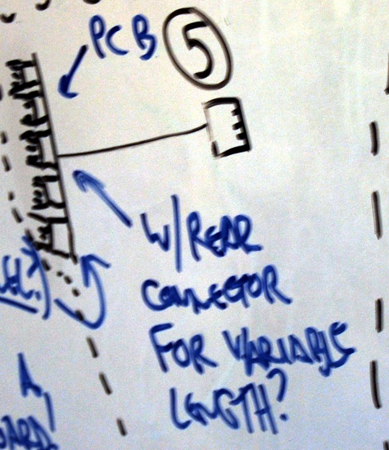
- New PCB concept drawing
![]()
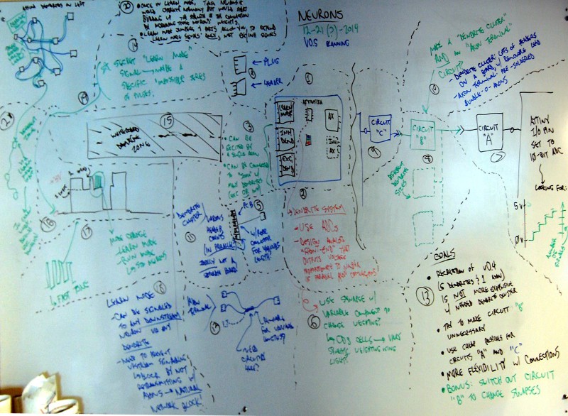
- ATtiny13A--the cheapest of the ATtiny series, and surprisingly it doesn't seem to be cheaper than the 44A in similar quantities. In any case--the idea is to back the I/O count down as much as possible. I suppose as pictured, I'd still need 8 I/O lines--three Dendrites (including the Learn Mode connector), two Axon options, and the RGB LED. Maybe the 44A is still the right call.
- Big deal here--each dendrite type has one connector rather than many. I'll get in to more details later, but this design includes some type of external splitter that allows multiple signals to feed a single dendrite.
- More on 'learn mode' later, too.
- The inhibitory axon is lower priority--that would complicate a lot of things but might prove interesting. Idea is--plug an Inhibitory Axon into an Excitatory Dendrite and it--does what? TBD, I suppose.
- Notes on the dendrite system
![]()
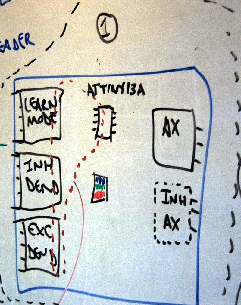
- So... the new dendrites will use the ATtiny platform's built-in 10-bit analog-to-digital capability. That means they'll be looking at voltage inputs between 0 and 5vdc.
- The analog front-end--that's the detail I'm conveniently skipping over here. This part of the system will convert simultaneous dendritic excitations into a proportional voltage response using some as-of-yet nonexistent circuit. One complicating factor--I still want exciters to work!
- Options for excitatory and inhibitory dendrites
![]()
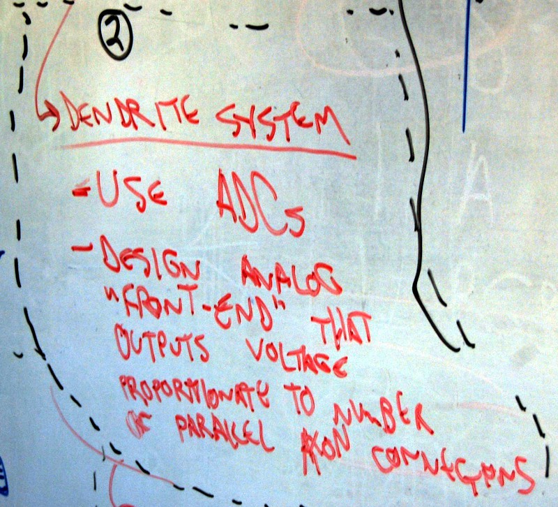
- See drawing (1) on the right? Yup, this relates to the two dendrites on v0.5.
- Here's the idea--I want to be able to plug a single unbranched (/simple) axon into either of these dendrites and have it work, but I also want to be able to split the dendrite. Maybe call the split version a 'soma', since that is the cell wall that dendrites branch out from?
- Drawing conventions
![]()
- Lest anybody gets confused, these are the 'schematic symbols' I'm using tonight. To be clear--plugs live on the ends of wires, while headers are soldered to PCBs.
- Dendrite expander idea
![]()
- This part could connect to the inhibitory and excitatory dendrite headers on the board. See? 1-to-5! Maybe I could make a few different standard split ratios--1:3, 1:5, 1:8, etc?
- One key idea here--separate the splitter board from the wire/plug. Not drawn but indicated with an arrow--splice a plug onto both ends of the wire, then put an input header on the board? Might bring down overall mfr costs and make everything a bit more modular?
- Thinking about synapses and weighting
![]()
- Linked via twisty arrow to idea (2).
- More far-out ideas here--making the axon-dendrite interface (synapse) something other than a 'perfect' conductor.
- If 'weighting' can be done using resistance--maybe use CdS cells as passive weighting components? I suppose cadmium doesn't go with RoHS, huh? Would the LEDs from other Neurons throw this off?
- Ideally--do 'weighting' in software (learning mode) AND hardware. How?
- v0.5 dendrite circuit (see below)
- v0.5 axon terminal circuit (see below)
- v0.5 axon (board level) circuit
![]()
- Pretty basic block diagram of a potential inter-Neuron circuit.
- Circuit "A", in the Neuron dendrite system, would convert the number of simultaneous inputs (either signals or exciters) into a proportional voltage, as shown in the graph on the lower right.
- Circuit "C", in the Neuron axon system, would allow each Neuron to add to the total voltage produced by "A" when its Neuron fires.
- Circuit "B" would allow multiple Neurons to send signals to a single downstream Neuron. What to call this? 'Soma'?
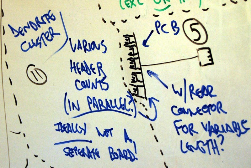
- Dendrite clusters and axon terminals
![]()
- Basic terminology--Dendrite Clusters are the input splitters shown in idea (5), while Axon Terminals are standard axons pre-soldered in parallel.
- More on dendrite clusters
![]()
- Yup, just added on to idea (5) here. Not much beyond the headers being in parallel with passive components as necessary (no microcontroller!). I want these to be scalable as needed!
- More on axon terminals
![]()
- I described this under idea (10)--just illustrated here. Ideally, everything is passive and in parallel like it is today!
- Do I need both Axon Terminals AND Dendrite Clusters? What about a 'splitter' and an extending Axon?
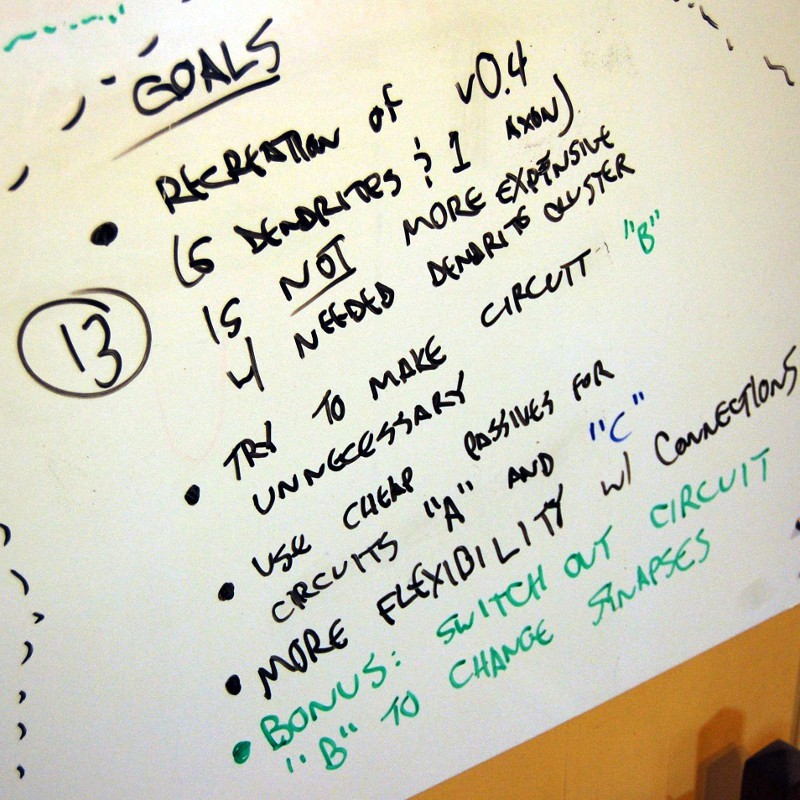
- Overall goals for v0.5--big picture
![]()
- Every Neuron version has been cheaper than the previous. Well, except v0.1. In any case, I don't want to break that cycle--as such, recreating one of the v0.4 units should not be more than ~$3.50 or so.
- In ideas (7), (8), and (9) I showed a proposed block diagram of the new interconnection system. If I can make circuit "B" in (8) unnecessary, then the "dendrite clusters" and "axon terminals" will just be parallel circuits--that makes manufacturing really simple and cheap and (hopefully) scalable.
- Cheap passives--circuits "A" and "C" are additions to the v0.4 design! Gotta make 'em as cheap as possible! That means no extra microcontrollers!
- More flexibility with connections--duh. That's the whole point. Some Neurons only have one dendrite. Some have TONS of dendrites. I need both options!
- The bonus would just be cool. Some kind of modular circuit that would change the weighting of a given input (or inputs). That gets closer to emulating real-world synapses--as in, not every connection is made equal.
- Can they learn?
![]()
- You can't tell in this image (refer to the master whiteboard picture at the beginning of this log update), but this idea is waaaay over on the other side of the board.
- Learn Mode signal--the best comparison I can make is the HART protocol, since it overlays a digital signal over an analog signal. Same idea here--dendrites and axons behave as they did previously, but they can also send a coded message that downstream Neurons will recognize to switch modes.
- Don't forget to remove blue painter's tape
![]()
- This happened when I taped a piece of paper to my whiteboard a few months ago. Normally I just avoid the area, but I needed the whole sheet for this brain dump--as such, it's marked as the Whiteboard Damage Zone.
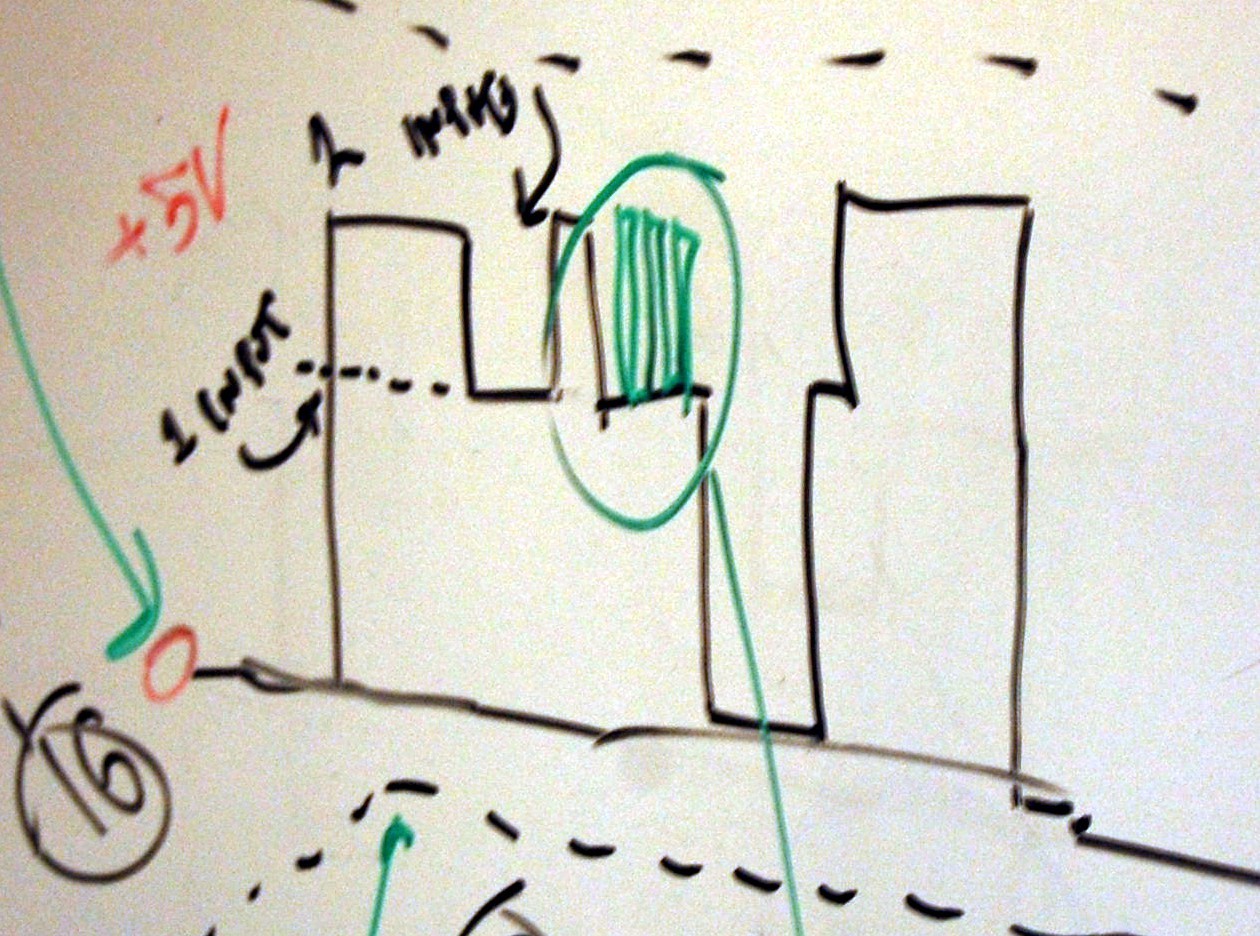
- Dendrite waveform
![]()
- Here is what you might see if you snoop a dendrite with a 'scope. Note that the voltage is quantized to a degree, allowing us to differentiate between the number of inputs sending active signals (exciters AND action potentials!).
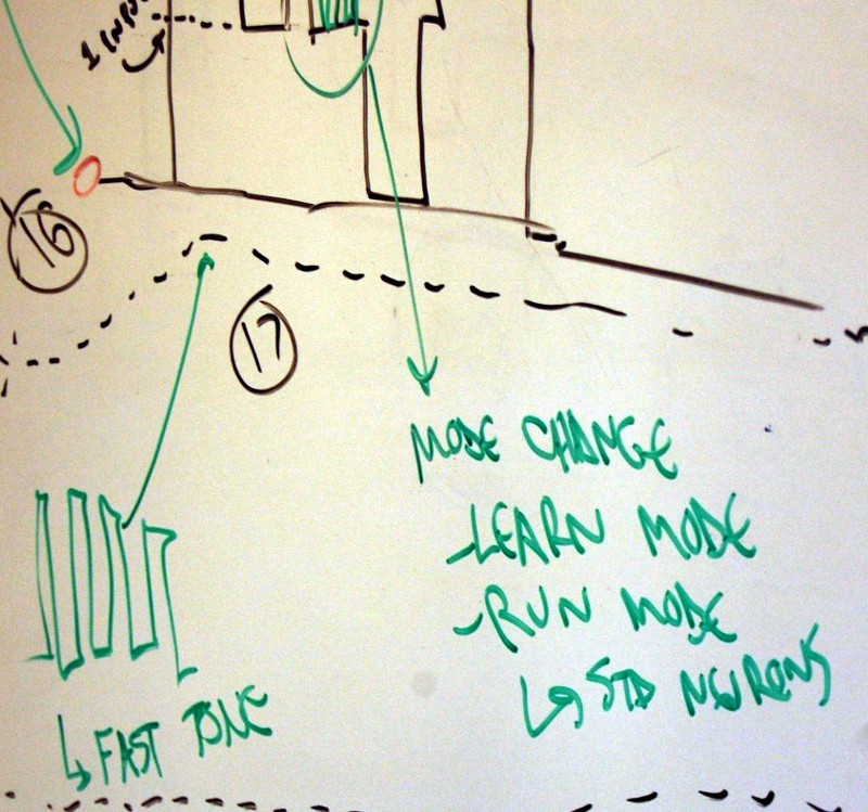
- Learn mode signal
![]()
- Extended from the previous image--the 'fast tone' just needs to be unique. As in, something that wouldn't be recreated by normal Neuron activity--maybe ten state changes in a certain number of milliseconds or something.
- How many modes? Maybe two--Learn and Run. Two different tones for different modes, or a toggling set up?
- Learn mode signal networking
![]()
- Should Learn Mode (and Run Mode) signal propagation follow the standard network? As in, if a Neuron is placed in Learn Mode, all downstream Neurons are placed in the same mode?
- Seems like electrically, the Learn Mode signal should propagate as we want it to without any special software considerations--all downstream Neurons would get the signals, but since Axons don't listen any lateral Neurons wouldn't get the message.
- What happens during Learn Mode? Maybe it's identical to Run Mode, but input weighting changes based on action potential frequency? How can we adjust input weighting when dendrites are in parallel?
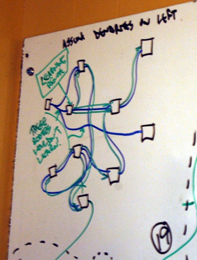
- Learn mode propagation diagram
![]()
- A bit blurry, oops. Black squares are Neurons, blue lines are standard Axon-->Dendrite connections, and green lines are Learn Mode signal propagation.
- New peripheral--the Learning Remote! Used to inject Learn Mode signals into a given Neuron.
- Learn mode features
![]()
- Also blurry--sorry.
- Describes what happens in Learn Mode--Neurons behave normally but would start increasing input weights.
- Again--how do we differentiate between individual Dendrite connections? Would this setup only work with unique inputs (as with v0.4)?
- Learn Mode Jumpers--connect standard signals to the Learn Mode input (see idea (1)) and ONLY Learn Mode signals will be 'heard'. Allows Learn Mode to propagate to non-connected network sections.
- Local/regional learning!
![]()
- This picture got a bit stretched and is super blurry. Sorry.
- This connects to the diagram in idea (19)--it just shows linking Learn Mode jumpers to a normally unconnected neural network.
- Seems like a 'bonus feature'.


Okay--back to v0.4 soon, I promise. With any luck, I'll reference these ideas when I take the next steps in v0.5 development. I think the analog input concept could improve network flexibility--it would be nice to have 10+ dendrite Neurons without specialized boards or programs. But for now, that's a solution lacking a problem.
Zach
Discussions
Become a Hackaday.io Member
Create an account to leave a comment. Already have an account? Log In.
A very great read. In a way this feels very similar, software-wise, to physics/fluid sims I've made in the olden days.
I wonder how hard it would be to implement this where each neuron is a pixel, on say a 64x64 LED matrix, and then simulate all the neurons in software, and put a photoresistor/button/some form of human input on each LED.... it'd be a giant interactive touch-LED-wall of neurons.
Are you sure? yes | no
Sort of like an FEA system? That's fascinating--I played around briefly in school with a few of these tools but never really got much more than a demonstration of basic features. I think a predefined neural network has some significant advantages--lots of Neurons that are easy to define in different ways, easy I/O, and so forth. I'm not sure how easy they are to hack, but there are a number of MIDI pads out there that have large matrices of illuminated buttons; I think I've seen 16x16 before, but that might be a bit expensive. Either way, one of the standard 4x4 units could be used to get software bugs out before building a big array.
One constraint with a 2-D array is that it's not easy to visualize connections that aren't fairly regular (i.e. next to each other); you could program the display to respond as a complex network, but it wouldn't be physically intuitive on the display itself. Writing a neat touchscreen driver for the program could be neat--figure out an easy way to navigate around 3D space, give yourself the ability to drop 'Neuron' nodes, and include tools for connecting and configuring networks of various sizes.
Either way, it would be awesome (in my opinion) to connect a software-based or LED matrix neural network to a physical setup like I'm building here; might give you the best of all worlds--complex connections via the computer program, and easy reconfiguring using the actual boards.
Speaking of which--I should get back to focusing on v0.4! I think there is still a lot to be learned from this generation.
Are you sure? yes | no
How many channels (if any) of PWM, ADC, digital I/O ?
I ask because while ATMegas are great for people making the transition from Arduino, PIC is king where cost and configurability are concerned.
It looks like the ATTiny44A has 8 I/O, and at least some PWM and 10b A/D converters for $1.34 in 100-unit quantities on Digikey.
Using Microchip's amazing tool: http://www.microchip.com/ParamChartSearch/chart.aspx?branchID=1005
We can find PIC16F1503 that has all of the same features at $0.75 in 100-count quantities.
If you don't need all of those peripherals, we can go even lower: PIC16F54 has the same pin count without the PWM/ADC channels and is $0.54.
Anyway. You get the idea, if you're willing to do a little more work.
Are you sure? yes | no
Are you sure? yes | no
How much does accuracy matter?
As long as the micro isn't really doing anything, bitbanging it is worth a shot. Try it on one of the ATMegas you have kicking around, first.
Are you sure? yes | no
I'm doing the 3 channels of PWM (for each Neuron's LED) manually on the ATtiny44A currently; it seems to work well enough, although I suspect I need to change timing parameters on one of the loops because I think it's getting slowed down. I'll keep your suggestion in the back of my mind--once I get closer to v0.5 I'll get my hands on a few PICs and start tinkering a bit. Saving BOM costs is critical, so this is quite helpful.
Are you sure? yes | no
Are you sure? yes | no
Why can't I directly drive the output from the resistor ladder--why is the operational amplifier necessary?
Are you sure? yes | no