 willbaden
Wanting to clean up the build, I have been slowly working on fitting the controller into a an old UPS box.
This is an old failed UPS that would be able to fit all the circuitry inside and leave plenty of room.
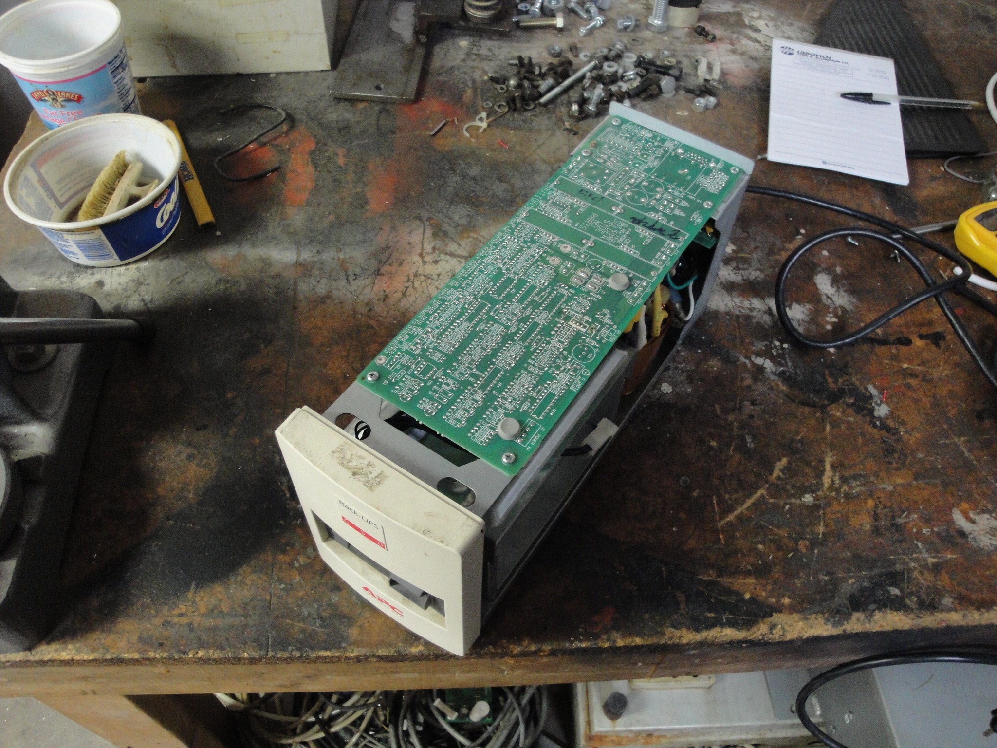
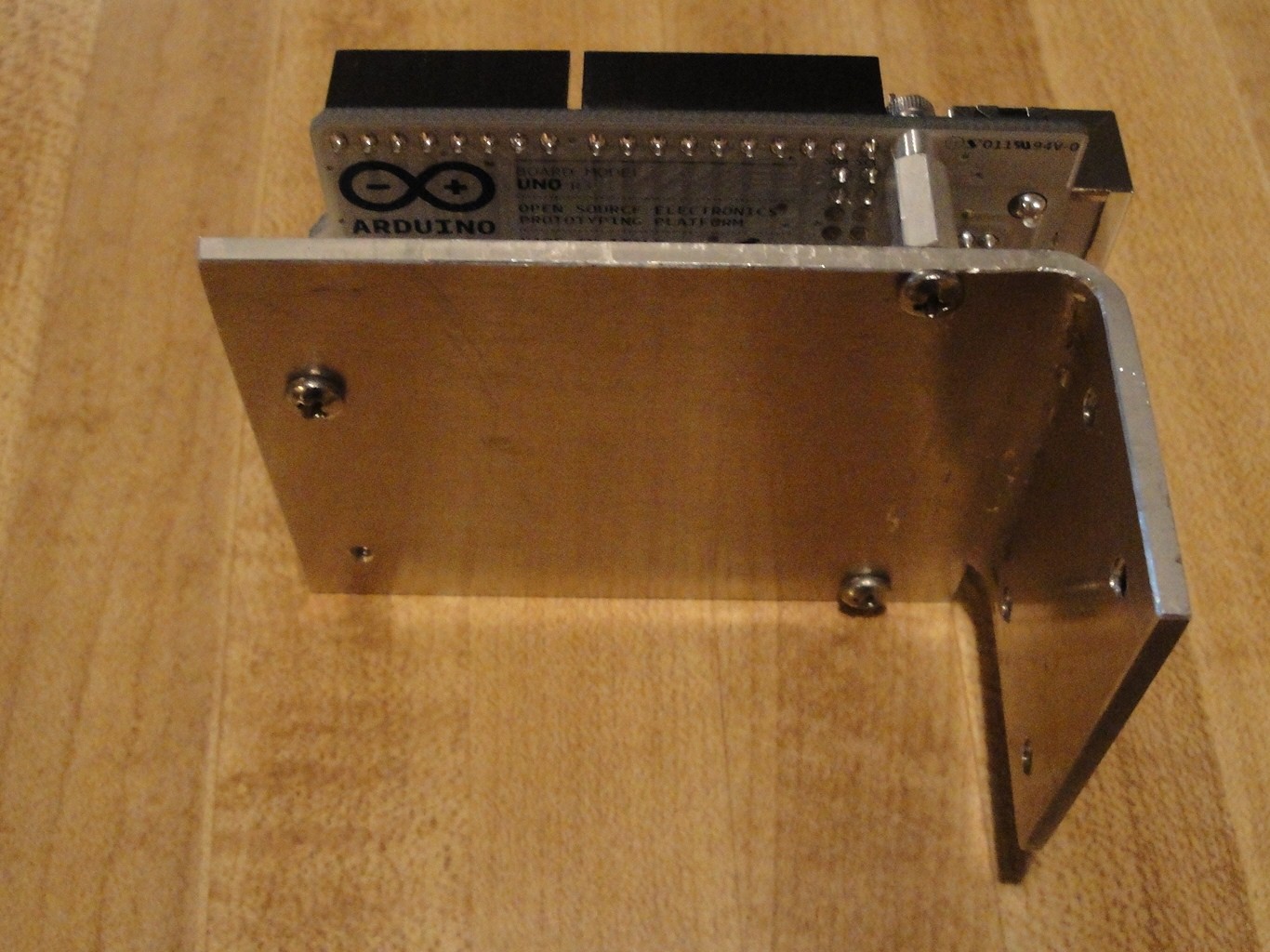
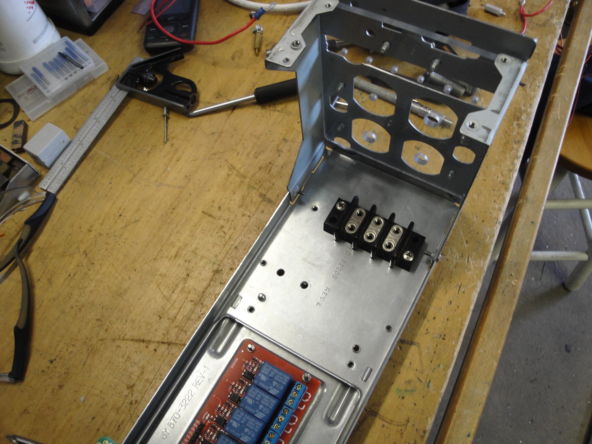
After gutting the UPS I could start placing components inside. First to find a location for the UNO. I wanted this to stay towards the front as the back panel had multiple holes from the UPS. It became apparent that a right angle mount for the UNO was needed. Below is a picture of the finished product. I used some 4-40 aluminum standoffs that needed to be turned on one side to allow for clearance of the pins. There is a screw missing in the picture, but it was included in the install.
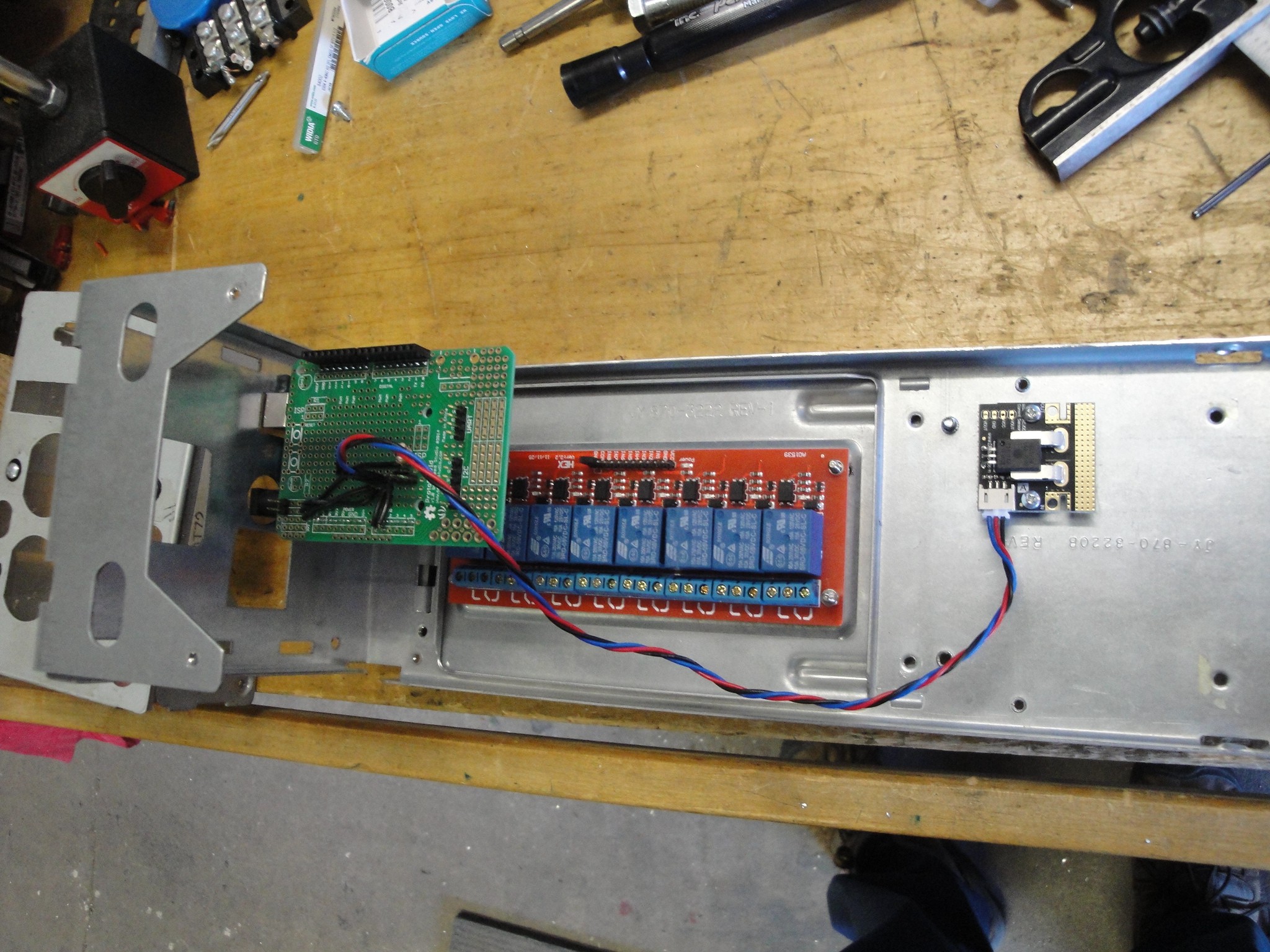
This mount was fastened to the front panel. There was a square port that allowed for the USB connection, but had to open a hole for the power plug of the UNO. Below on the bottom is the relay board. It is using some 6-32 standoffs I made for a different project and just repurposed. Moving to the right is the current sensor. I used some Delrin to mount the current board to. It has four holes, two patterns. One set of holes for the current board mount and one set to mount the delrin to the box.
Looking at the back of the box, I mounted a terminal block that will be used for the 12V side of the circuit. In the picture, the clear plastic mounting for the lugs of the outputs can also be seen.
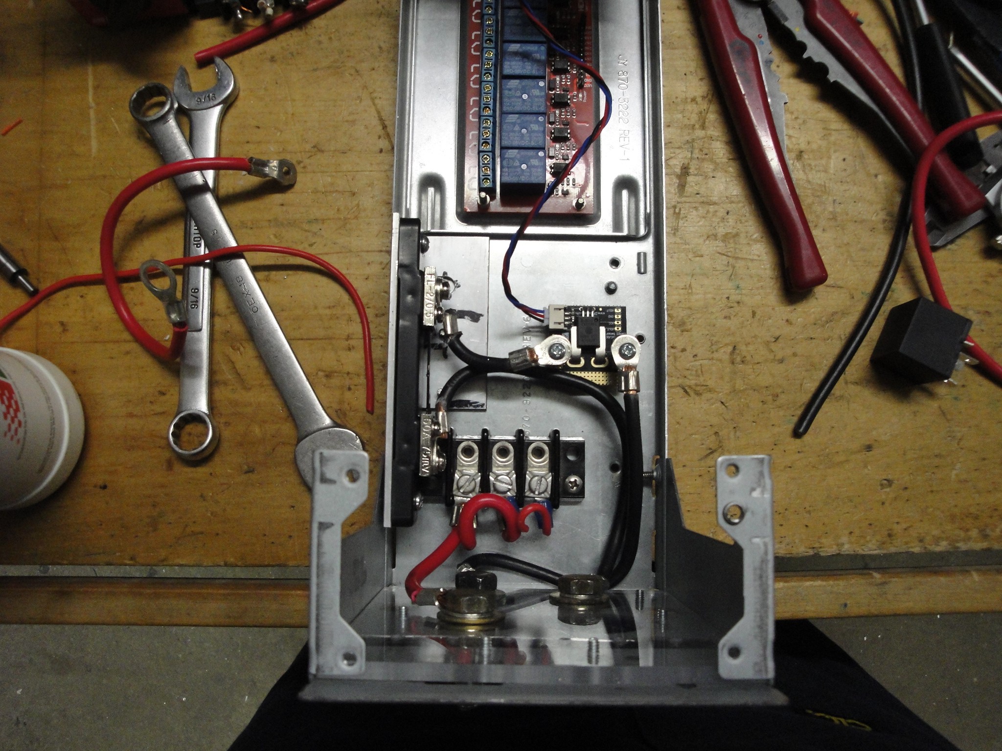
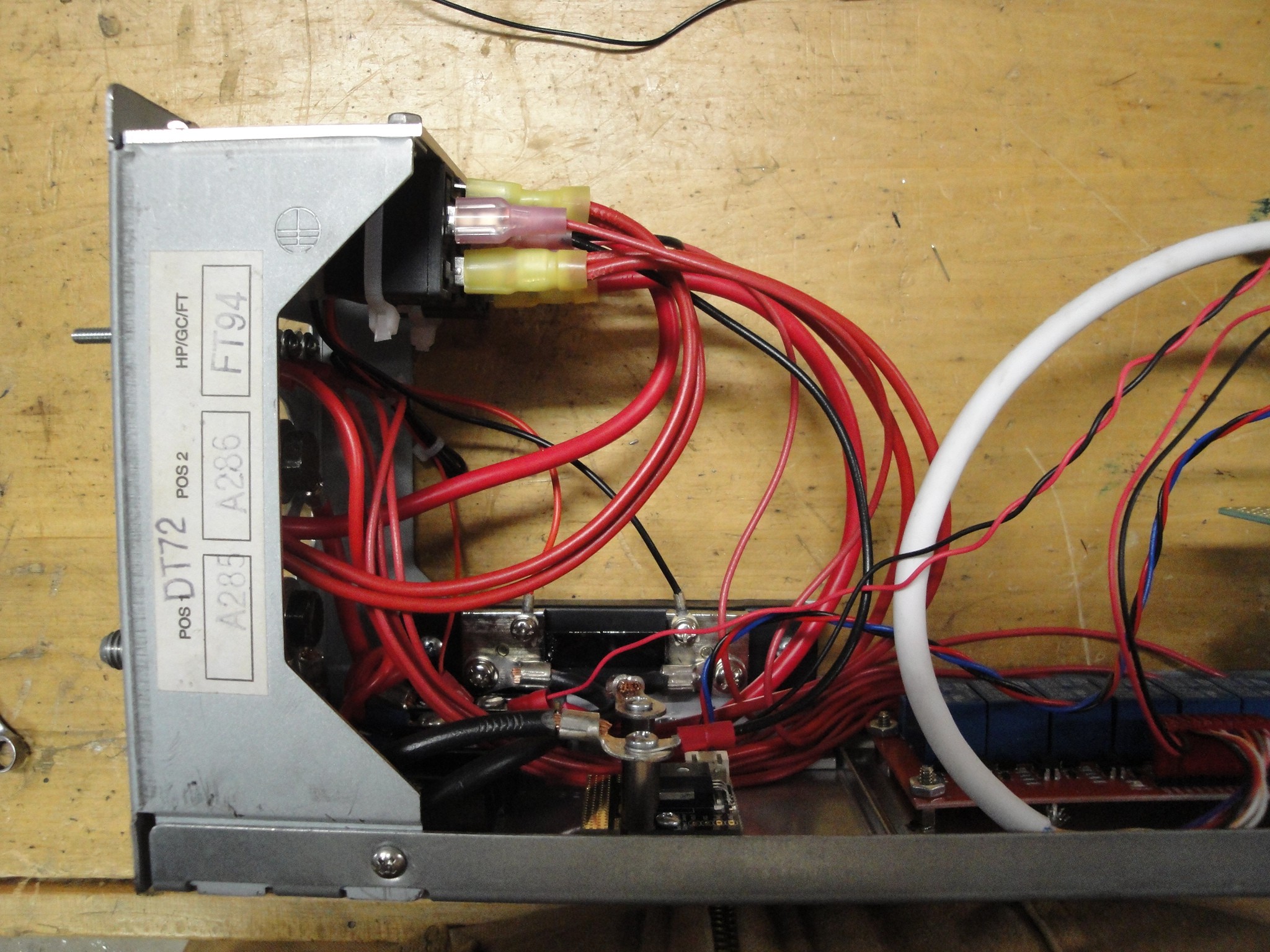
When testing the current sensor circuit, I was not satisfied with the consistency of the current readings. As a fail safe I added a 50A shunt ammeter. This will be a double check that the calculations the UNO is producing is the same as a dedicated ammeter. The shunt can be seen in the below left. It is the long black strip with the black wires coming off of the silver blocks. The ground from the 12V battery is fed through the hall effect sensor the UNO uses, then is fed through the added shunt, and finally fed out the back of the box to be fed as a common to the testing loads.
Here is a mid build picture as the wiring is being added.
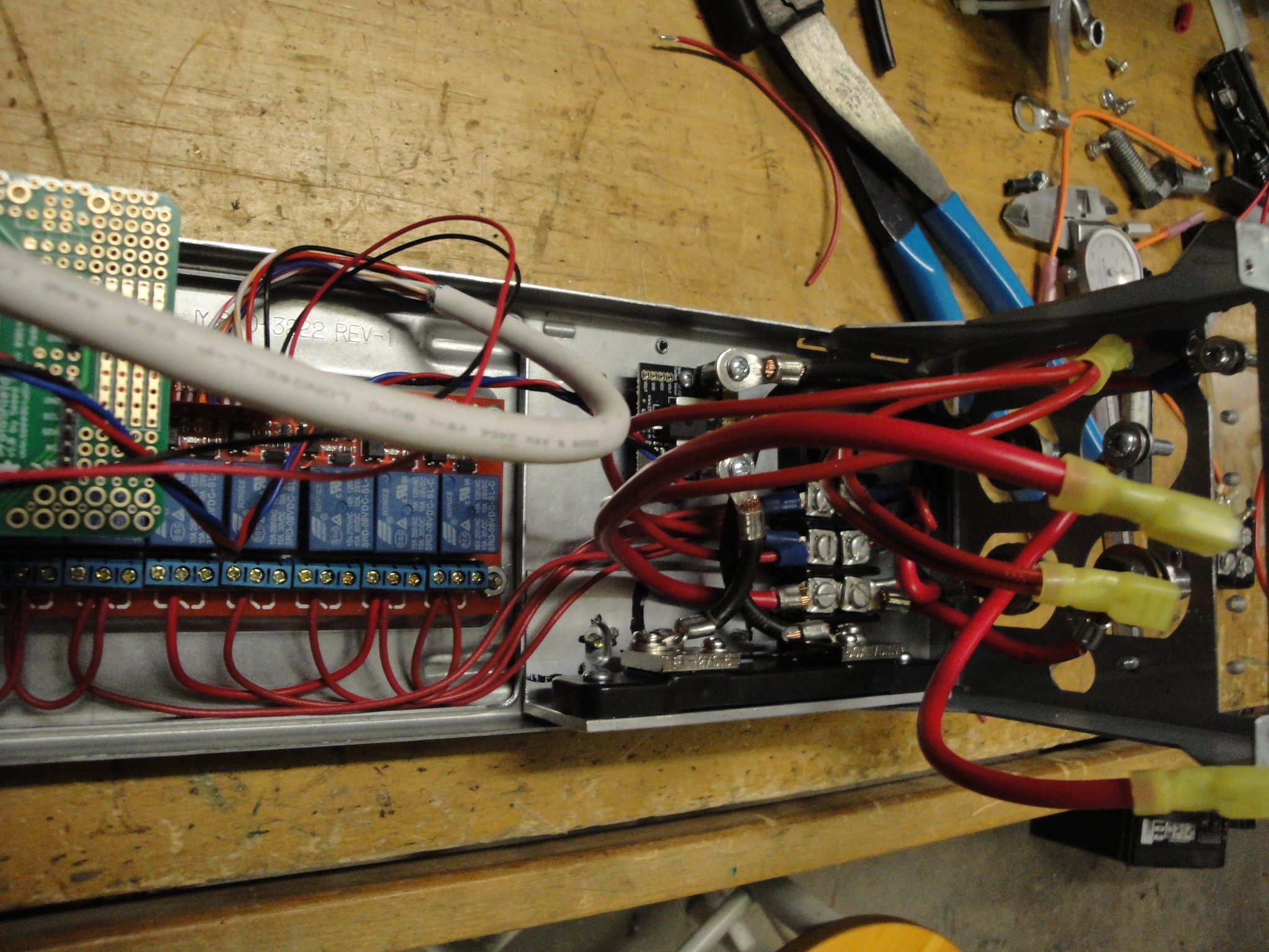
Finding a place for the shunt ammeter LCD was another trial, but ended up working out placing on an aluminum plate that also has the high amp relays. The relays are below the plate with the connections to the left (large yellow connectors). Using the undercut feature of CamBam allowed for easy installation of the LCD display.
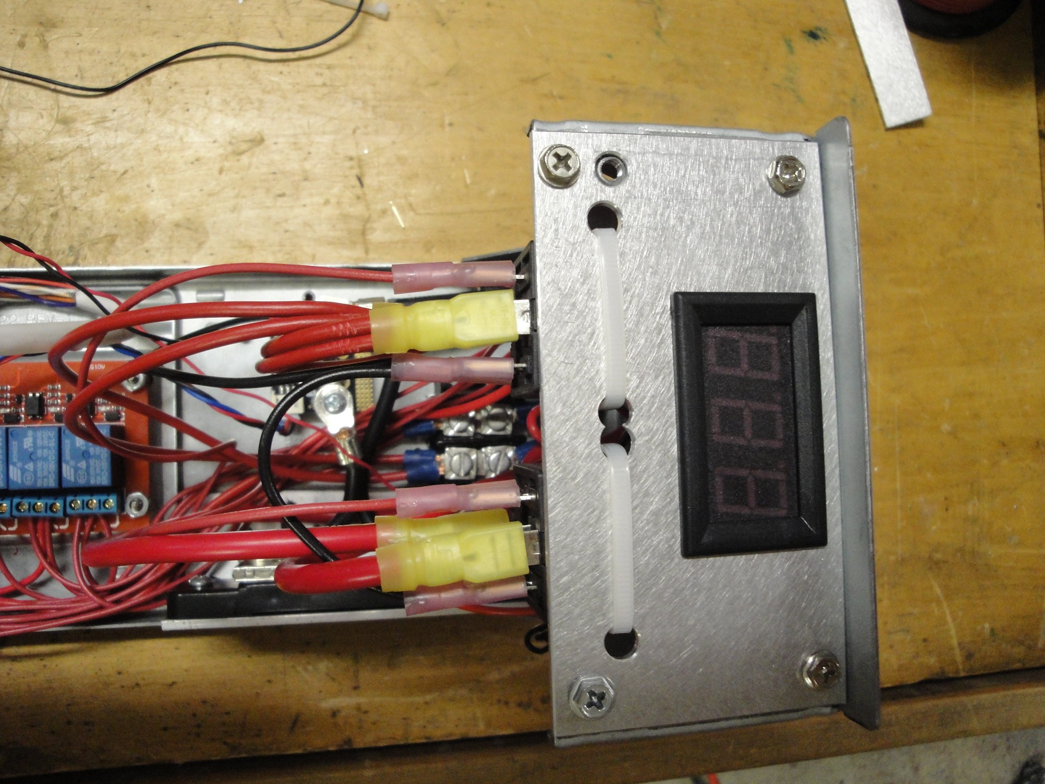
Here is a side overall view of the top plate with the relays underneath:
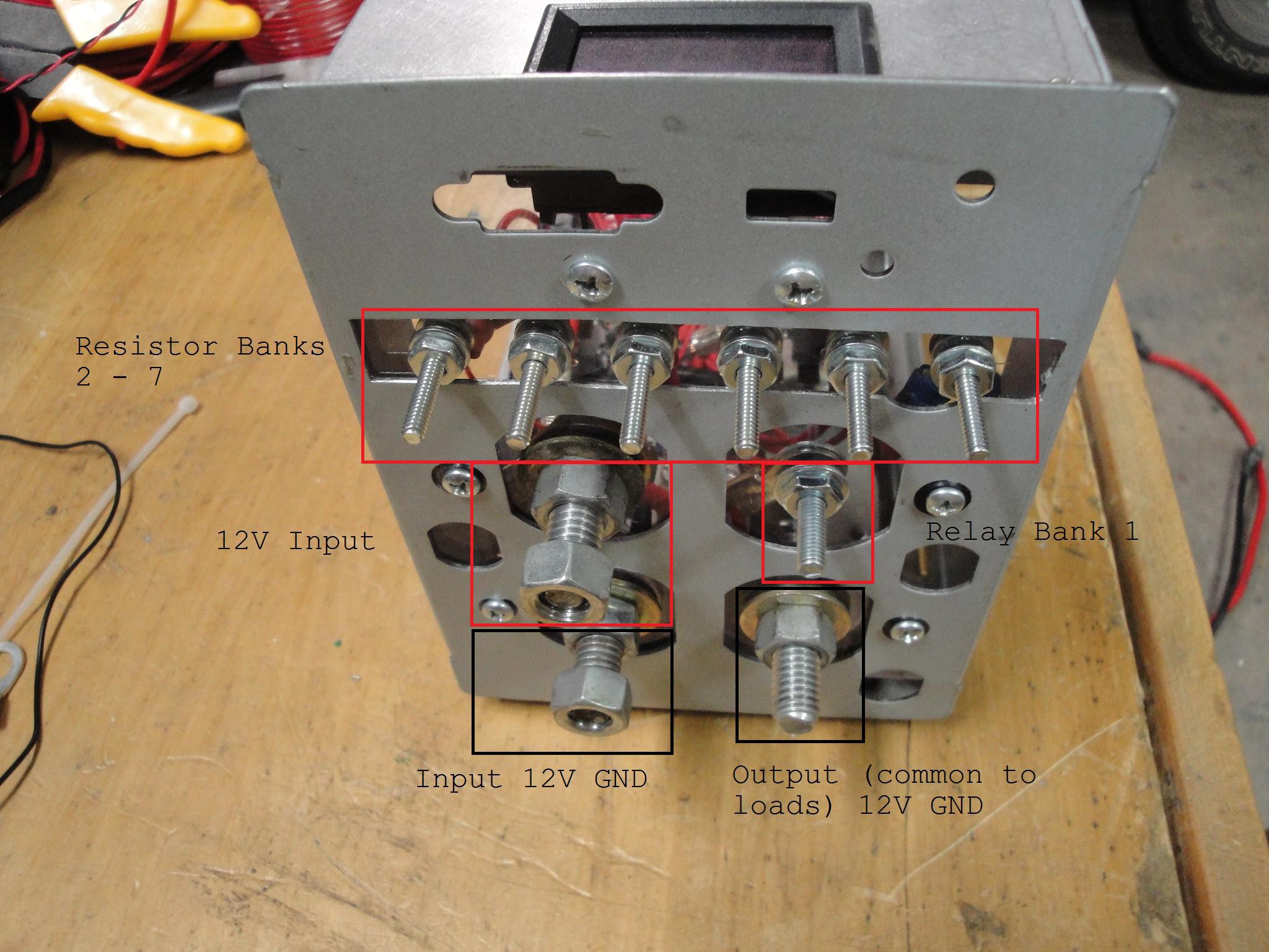
To allow for easy attachment of varying loads, I ended up with a lug of connections. Smaller screws for the smaller loads and a larger screw or the larger load. The top row is the outputs for Resistor banks 2-7 (left to right). Below the row on the left is the positive input (battery) lug with the negative input (battery) lug below that. On the right, just below the row of resistor bank outputs, is the lug for resistor bank 1. The lower right lug is the common (12V gnd) to be fed to all the resistor banks.
This has been tested to the point of relay/UNO operation, but it has not been tested in a loaded scenario. Prior to running that test, a resistor bank box is being built to make for easier use.
Discussions
Become a Hackaday.io Member
Create an account to leave a comment. Already have an account? Log In.