Close
0%
0%

Search Logic voltage levels

Faster than a voltmeter for detecting logical levels

Similar projects worth following
The highlighter has a tip amended able to read the voltage level at a point of an electric circuit.

This voltage is compared to a voltage level equal to 5V, if the voltage is equal to or higher than 5V then the LED RG on the back highlighter becomes green, indicating a high logic level (TRUE), otherwise the led becomes red RG , indicating a low logic level (FALSE).

This device is faster than a voltmeter in the search logic levels as it has a particular tip which allows rapid insertion of the breadboard, breadboard and printed circuits, by directly reading the logic level on the pins of the various components of a circuit.
It is also powered by the same voltage taken from the circuit on which to read the logic levels.

https://mipstudioblog.wordpress.com

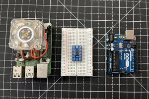
The circuit is very simple.

The heart of the device is a voltage comparator TLC3702IP able to compare the voltage levels on its input pin , emitting a voltage level output based on the result of the comparison.
On a first pin reaches the voltage read from the tip ( nail welded copper , excellent electrical conductivity ) , on a second pin instead read a reference voltage for the high logic level , in this case 5V .
Here the formula that determine the level of output voltage :

Vout=+Vcc.if.(V_i  data-verified=

Vout=-Vcc.if.(V_i < V_r)

  • + Vcc is the positive power supply voltage ( 5V )
  • -Vcc is the negative power supply ( GND )
  • Vr is the reference voltage for comparison

This control Vout goes through an additional circuit , an RG LED (LED 3-pin ) that glows red to green and low logic level to a high logic level.

  • 1 × TLC3702IP Amplifier and Linear ICs / Comparator ICs
  • 1 × RG Led
  • 1 × nail welded copper
  • 2 × cable
  • 1 × glower case

  • 1
    Step 1

    Find a glower case and destroy it

  • 2
    Step 2

    Create a circuit based on TLC3702IP

  • 3
    Step 3

    Link the tip to an TLC3702IP input

View all 5 instructions

Enjoy this project?

Share

Discussions

M.i.P.studio wrote 06/29/2016 at 17:54 point

K.C.Lee I don't understand what you write, bad documentation and bad explanation...

  Are you sure? yes | no

K.C. Lee wrote 06/26/2016 at 14:09 point

Multiple things that are wrong with this design.  See datasheet.

- Common mode voltage of TLC3702 is Vcc - 1V (min) at 25C so it cannot be trusted to compare voltage above that point.

 - Input range is  up to Vcc only.  Need input protection or voltage divider of some kind.
- Are you trying to look at logic levels instead?  If that's the case use VIL, VIH for valid leverls.  Use Vt if you only use 1 comparator, but you cannot tell is level is valid.


  Are you sure? yes | no

Dom wrote 01/07/2015 at 13:05 point

Nice, simple, practical and solidly executed: what's not to like?
Most projects here try to bring so much things under the hat it's ridiculous, this is just a thing that owns itself.

If I may make a suggestion: I would instantly slap a piezo buzzer and some pots on here for good measure.
Why? Ears need no visual line of sight for example. The pots could parametrize the threshold/trigger levels, for example doing quick checks on the rail voltages. But that's just me tough.

  Are you sure? yes | no

M.i.P.studio wrote 01/07/2015 at 19:05 point

Yes, the piezo can be a good implementation

  Are you sure? yes | no

Similar Projects

Does this project spark your interest?

Become a member to follow this project and never miss any updates