This project is a guide or inspiration to make your own fan controller to your Re:Load Pro.
It uses the expansion slot on the PCB, so no need to hack to get the fan controller PCB connected to the Re:Load Pro pcb. Macked on the image below.
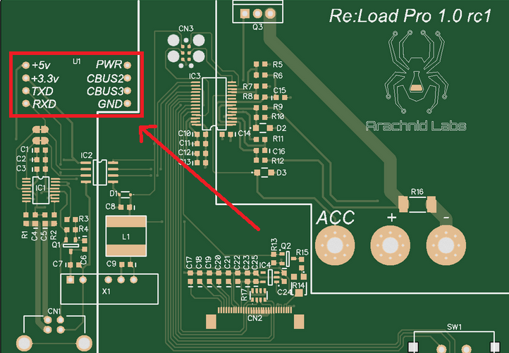
This expansion slot have both power and TX and RX from the FTDI chip, and it got me to thinking whether the UART interface could be used to something useful. And the idea I got was to make the control variables customizable via the USB interface. The RX line was already used by the uC on the Re:Load Pro, and I didn't wanted to interrupt any communication from the load to the PC. So only the TX line is available that means that the fan controller on can receive data from the USB interface.
When the USB not could be used to give response back that the a control variable was successfully sent and received, and I did not want to add any other components, did I only have one other another solution. The only solution to the problem was to use the fan to give a "OK" received response. This is done by setting the fan on with full power for 500ms, and this give with the fan I use a notable audio feedback.
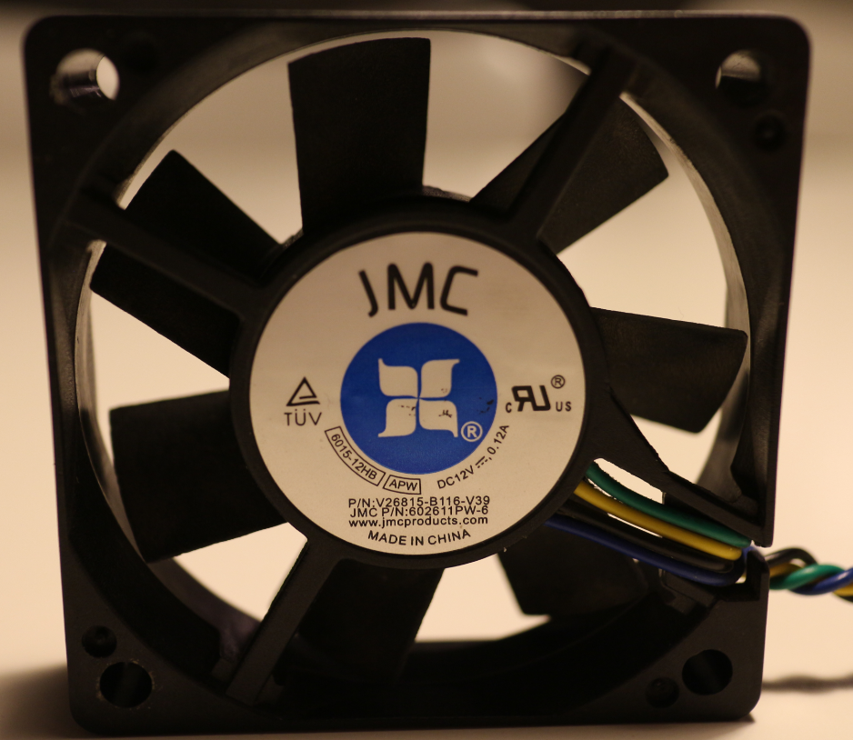
FanThe fan I use is a PWM controlled fan where the fourth pin on the connector is used to set the fan speed, with a PWM signal. This PWM signal is generated by the ATtiny uC with a frequency on 21kHz, and this is just within the acceptable operational range. For what I could find on the internet how to control a PWM controlled fan, is the PWM frequency range: 21 kHz to 28 kHz.
This fan is 60mm x 60mm x 14mm and just fit the dimensions of the heat sink on the back on the case, that also is 60mm high. On this heat sink there is two M3 threads that just exactly fit to two of the holes of the fan. For mounting the fan to the heat sink you just need two M3 bolts, this just hold the fan in one side, but if your want you could also glue it in the other side, but I think it's rigid enough with only two screws.
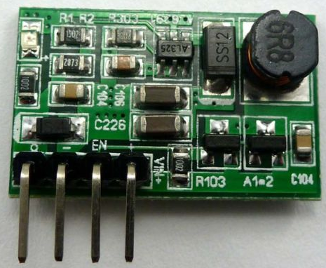
The boost converter I use is just one I found on ebay that is reasonable small to fit inside the box with plenty of space to spare. This can deliver 370mA with 5V as input and should be enough to the most 60mm fans. This board has also a pin capable of switching the converter on or off by setting the pin high or low, and this feature make the fan controller capable of switching the fan completely on or off .
It has a 90° header that I removed, and solder some solid wire in instead, so it could be soldered to the pcb I had made.
Temperature Sensor
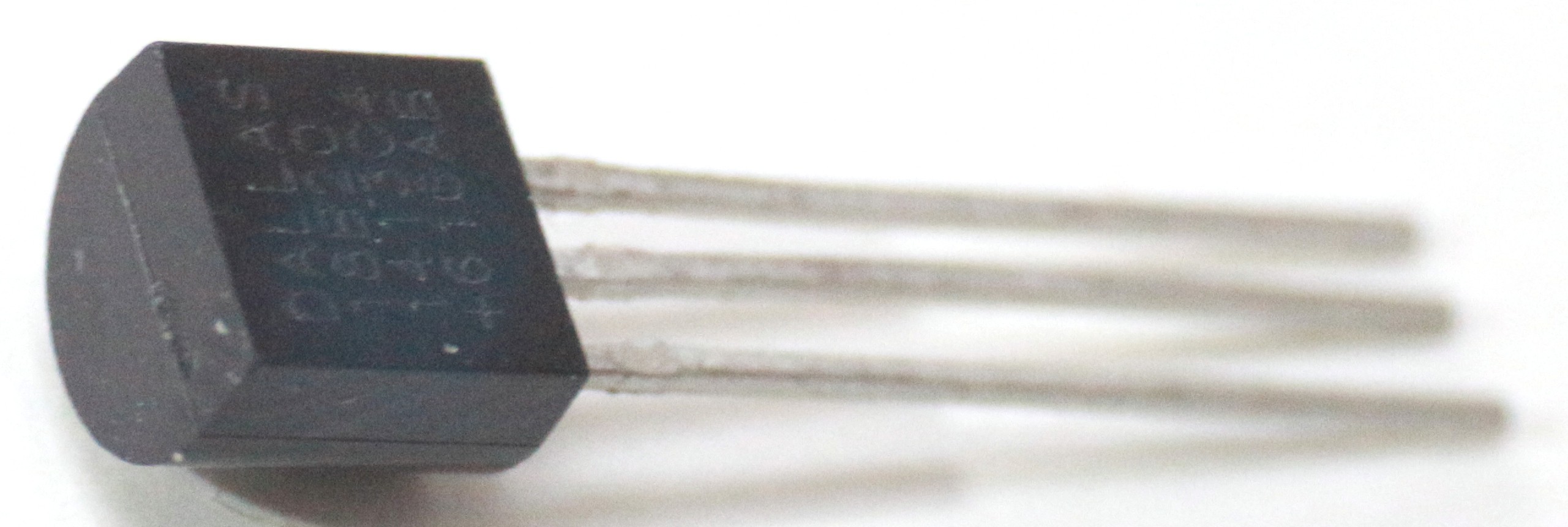
The temperature sensor used is a DS18B20 that provides a 12-bit temperature measurements in a of range of -55°C to +125°C over a 1-Wire bus. This is mounted on the heat sink behind the fan.
Microcontroller
The uC i choose to use to this project is a ATtiny2313A and have 2KB flash memory.
The code the uC is executing get the temperature reading from the temperature sensor and from that calculate if the fan should be switch on or off and how fast it should be spinning. This is done by 5 values:
1. MAX: The temperature where the fan is running at max speed (100% duty cycle).
2. MIN: The temperature where the fan is running at min speed (MIN DUTY).
3. START: The temperature where the fan is turned on.
4. OFF: The temperature where the fan is turned off.
5. MIN DUTY: The minimum duty cycle the fan can get when turned on.
These 5 values is fully customizable in a range of 0-99°C except of the last that sets the minimum duty cycle in %.
When the measured temperature is between MIN and MAX. The duty cycle will be set to a value determined by a linear regression by these two temperature values. As shown here:
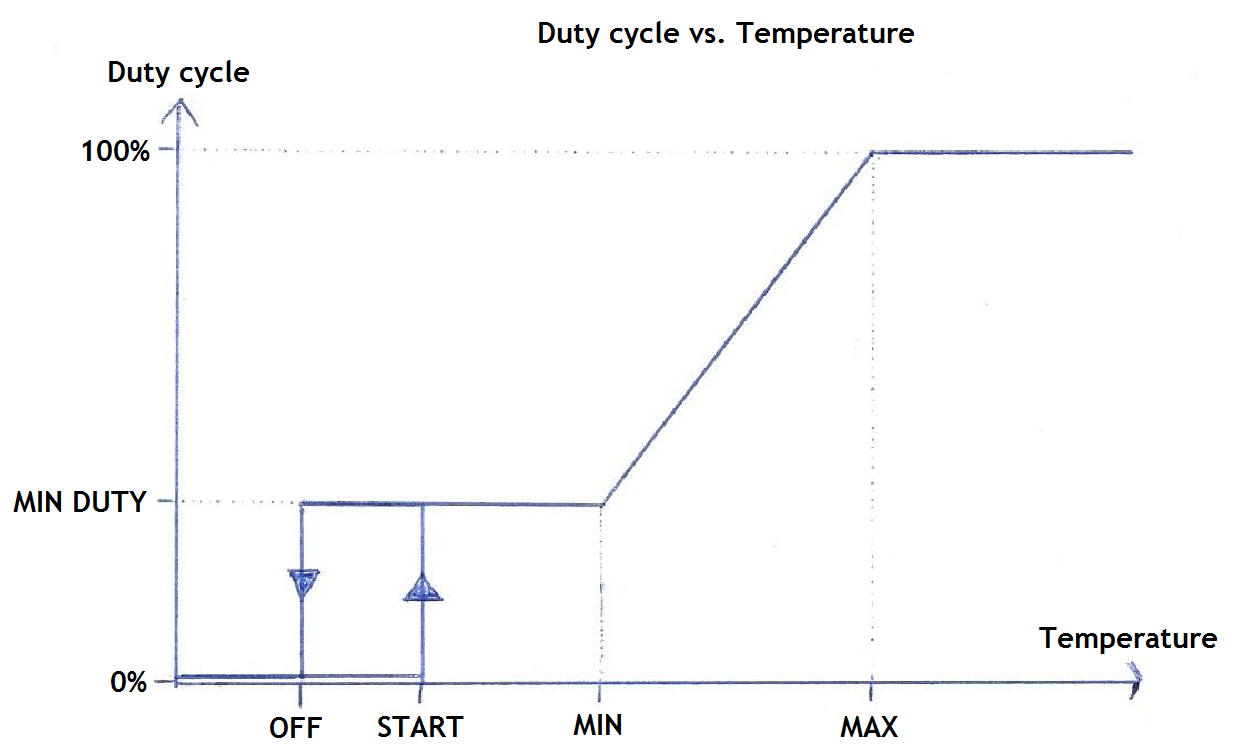
In this diagram your can also see it is possible to use hysteresis based switching to turn the fan on or off.
Through the USB interface of the front of the Re:Load Pro can all of these 5 values be set. The values is set by sending text based commands as follows:
"FA2_37": This command set value 2 (MIN) to 37°C.
"FA5_09": This command set value 5 (MIN DUTY) to 9%
If the the value is recived and understood by the uC, the fan will be turn on for 500ms with 100% duty cycle. The value is then stored in the EEPROM, and is loaded on every power on.
PCB
The PCB I have made with my cnc machine by milling the top copper off. There is many different ways to make your own PCB, and is only single sided so it should not be to difficult to make yourself.
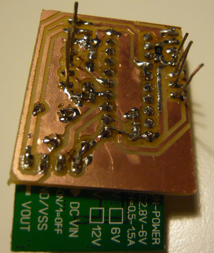

These pictures correspond not completely to diagramet and print layout, since I in the meantime have made PCB new version where electrolytic capacitoreres has moved a little, and now also with a freewheeling diode over the fan.