 Kuro
KuroProject files: soldering station files
0%
0%
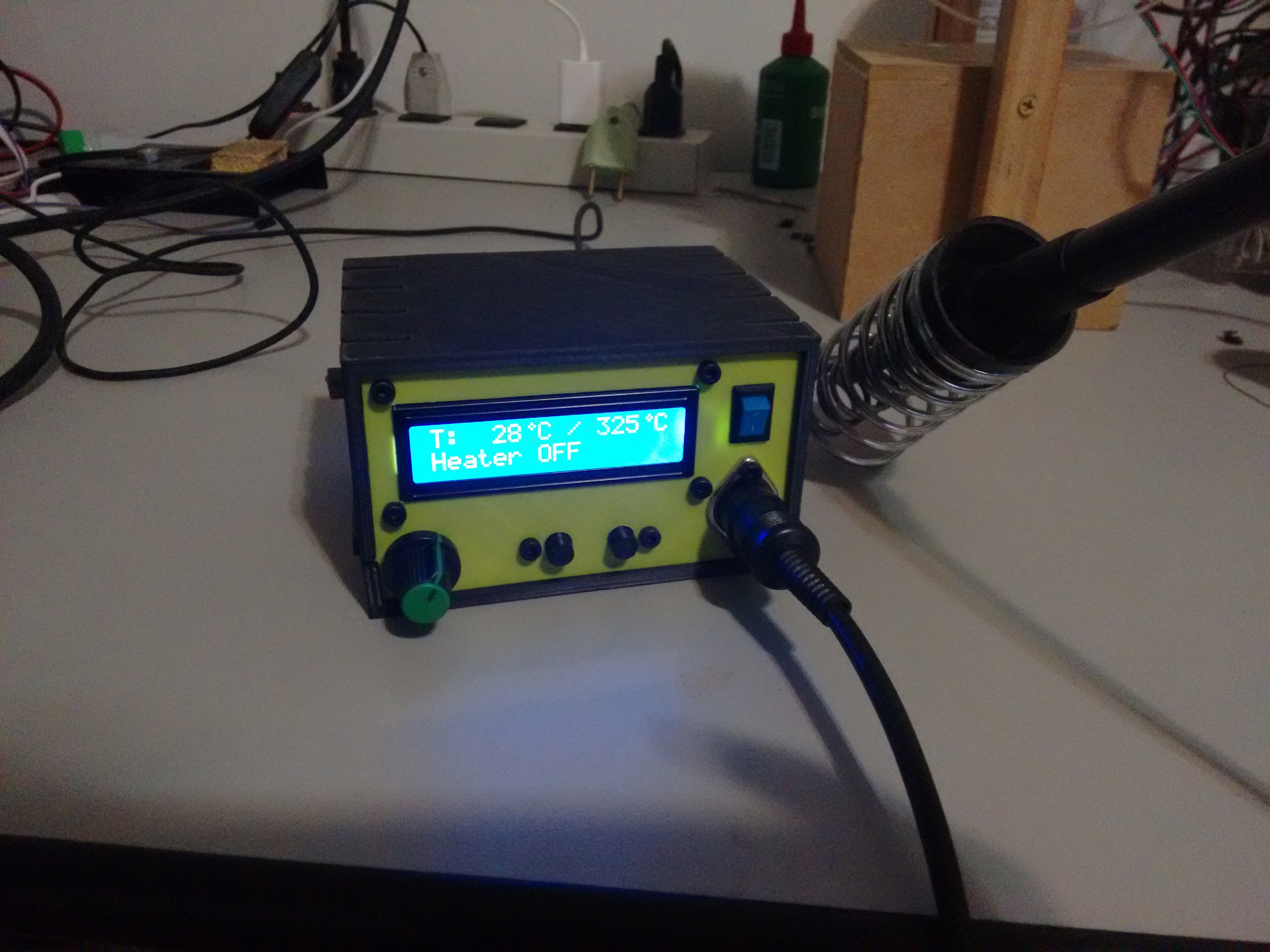
Hakko 907 based Soldering Station
A soldering station based on the easy to source Hakko 907 soldering iron, which is a 24V 50W soldering iron with integrated thermistor.
Become a Hackaday.io member
Already have an account? Log in.
Just one more thing
To make the experience fit your profile, pick a username and tell us what interests you.
Pick an awesome username
hackaday.io/
Your profile's URL: hackaday.io/username. Max 25 alphanumeric characters.
Pick a few interests
Projects that share your interests
People that share your interests
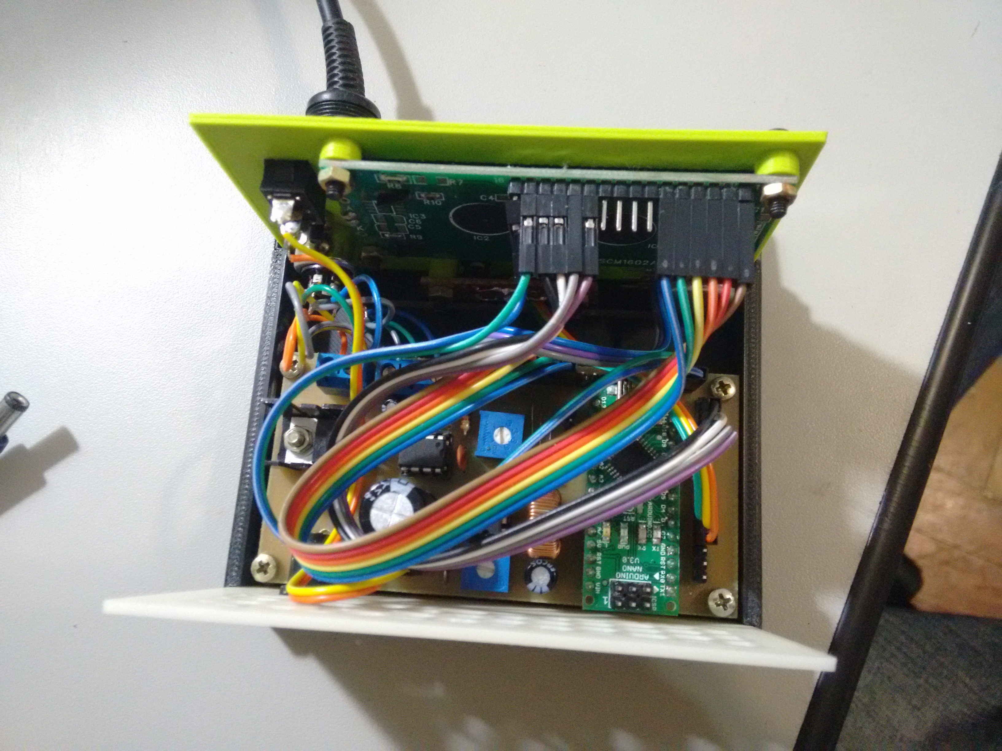
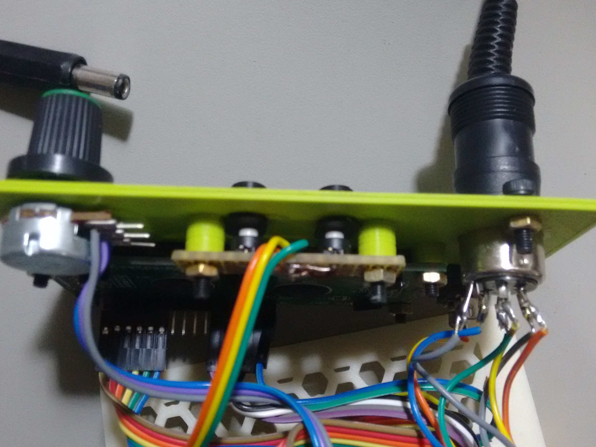

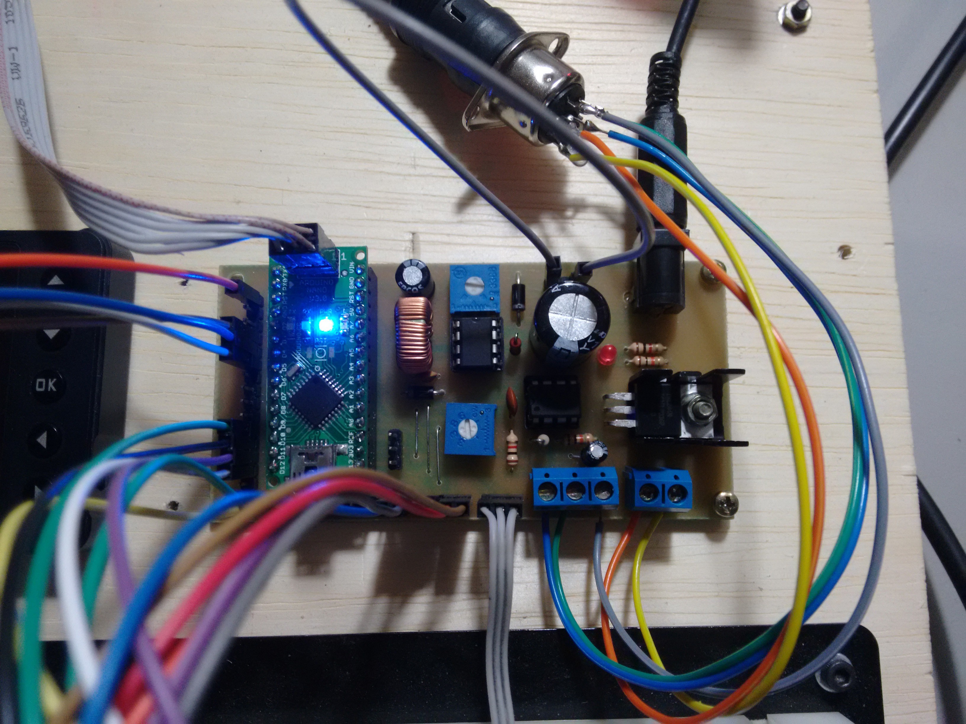
 Then, I went to finish the switching power supply. Power jack, power switch connections and capacitor.
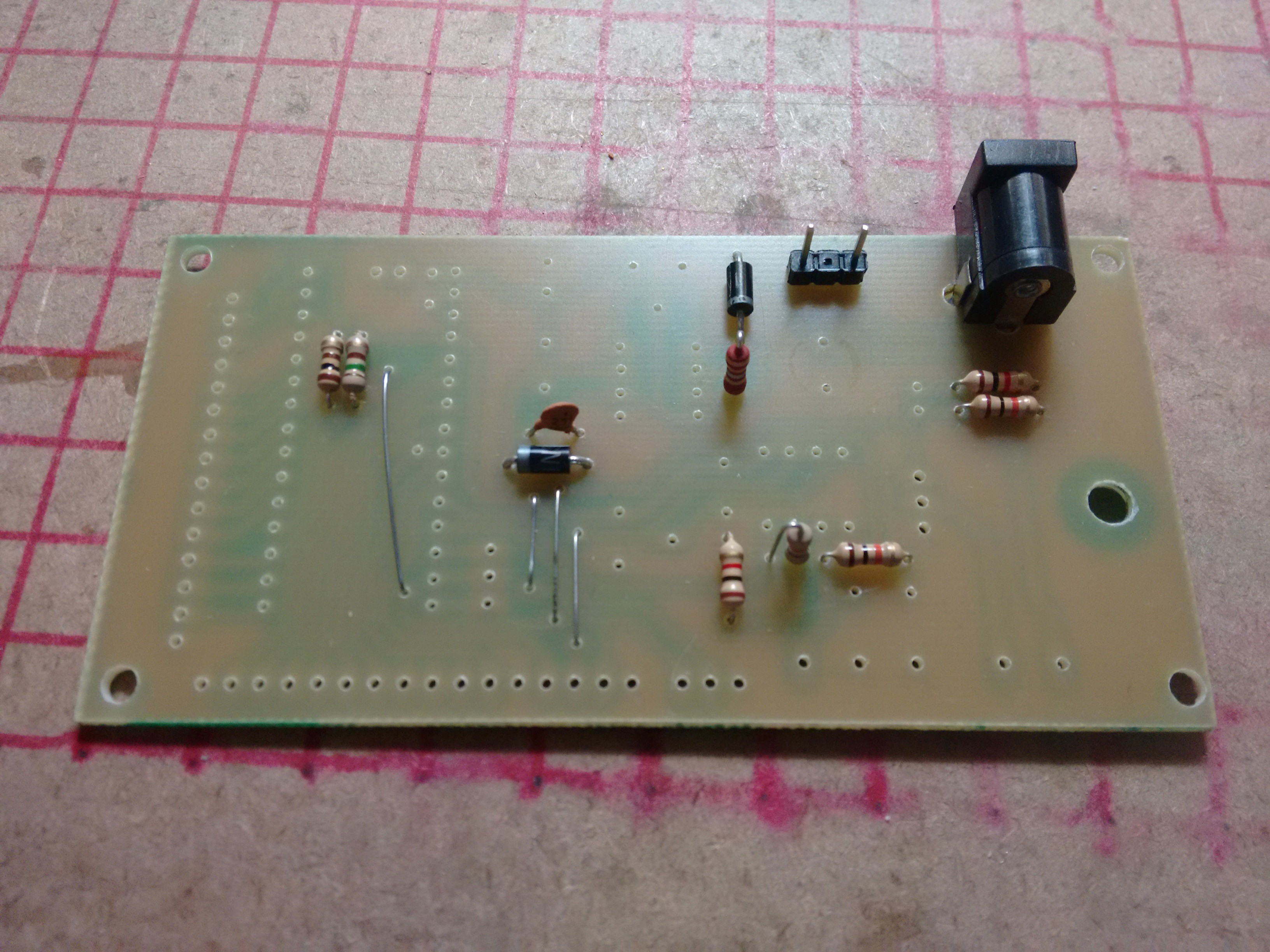
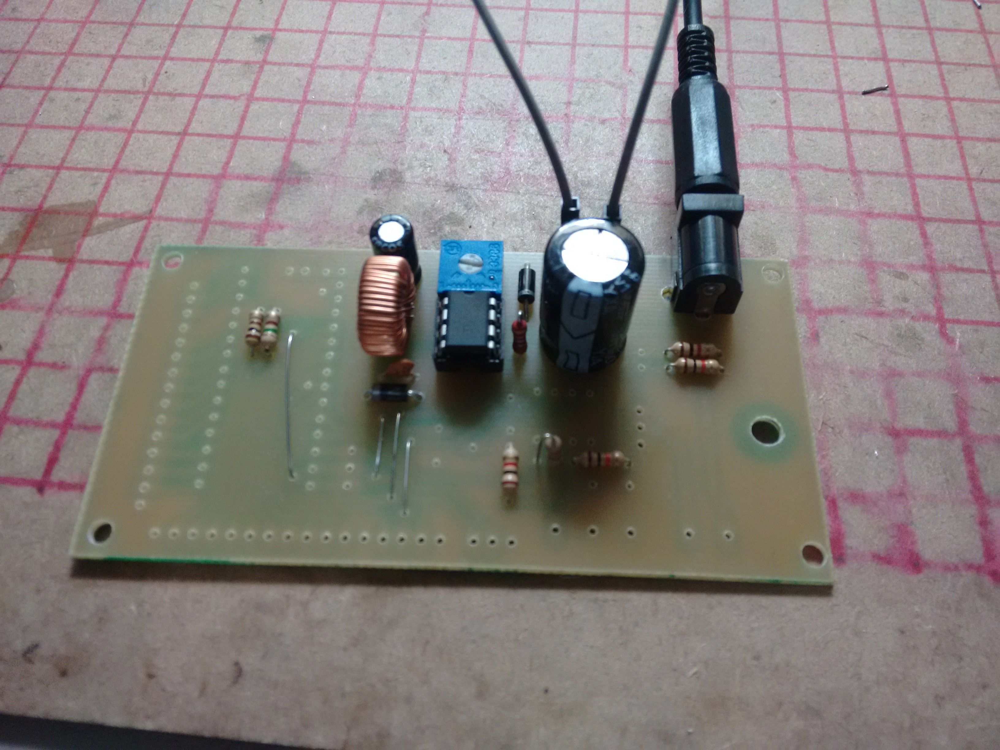 Everything working alright. I set the output voltage to 12V with the potentiometer. You want to set the output voltage now, because if you connect your Arduino without setting the voltage first, you could fry it.
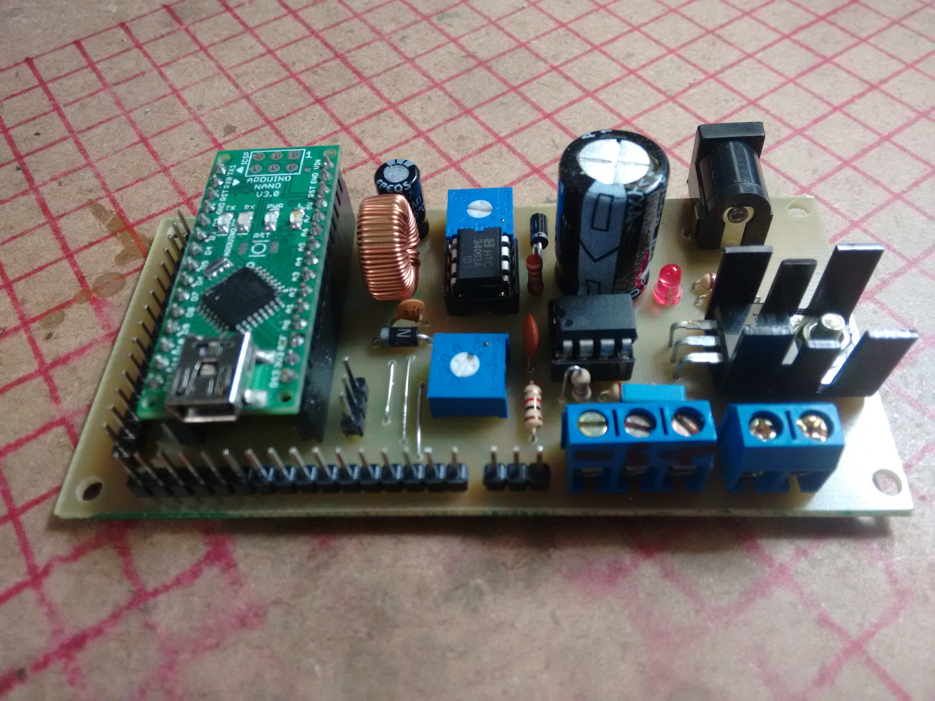
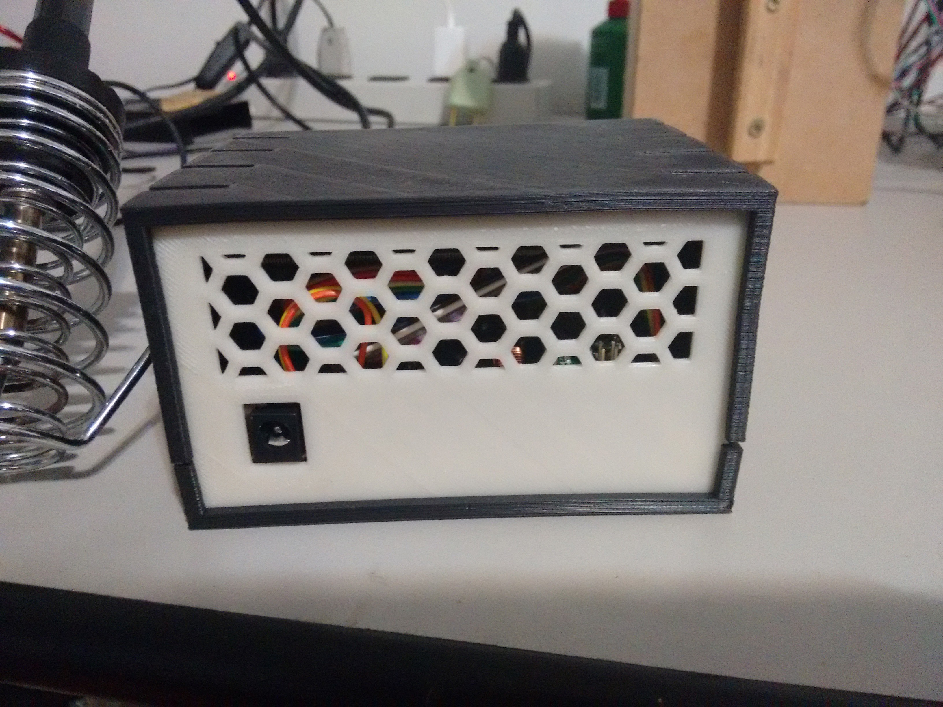
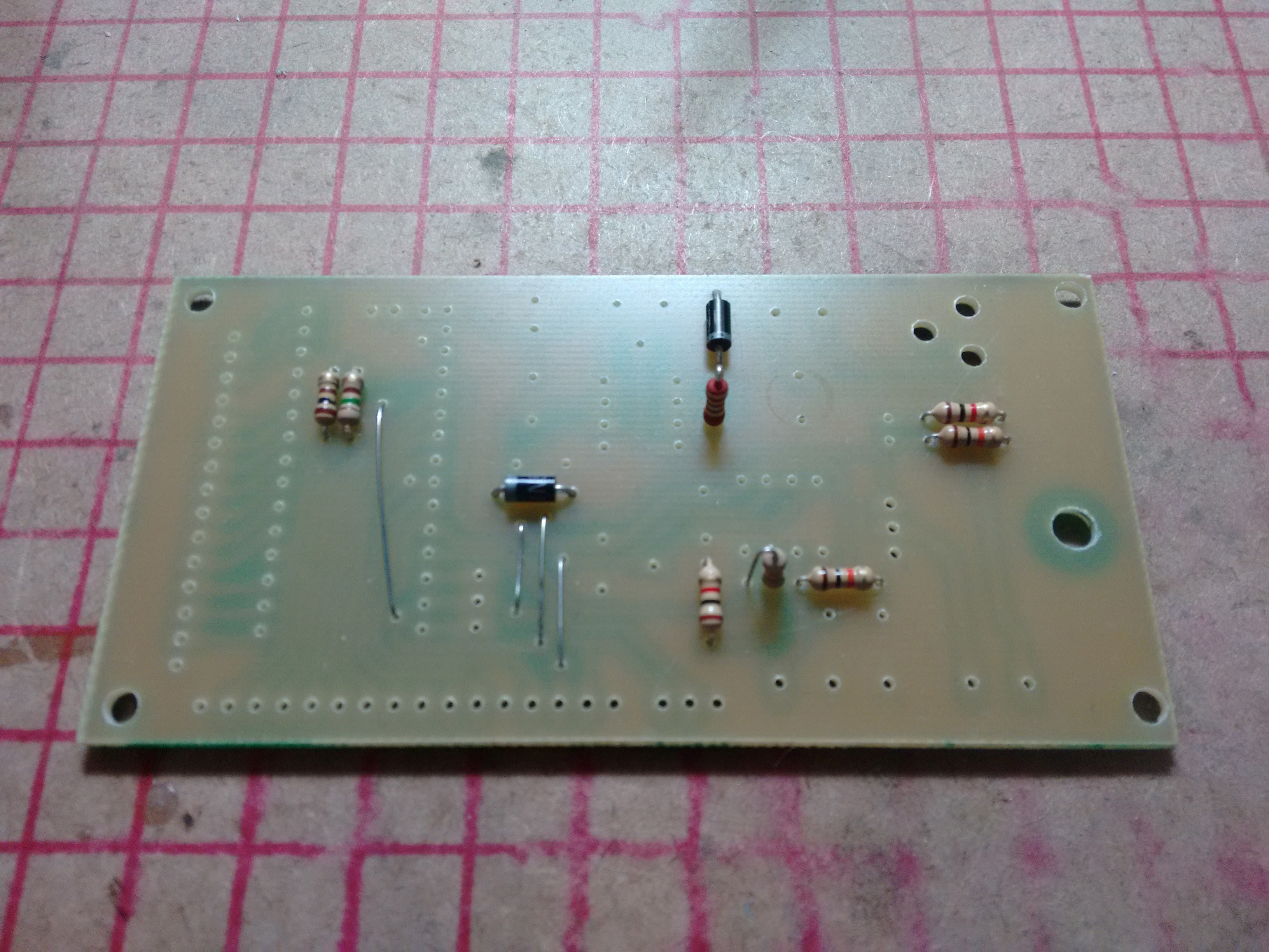
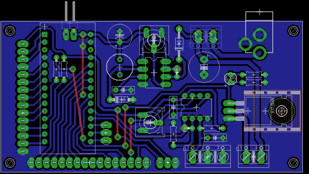
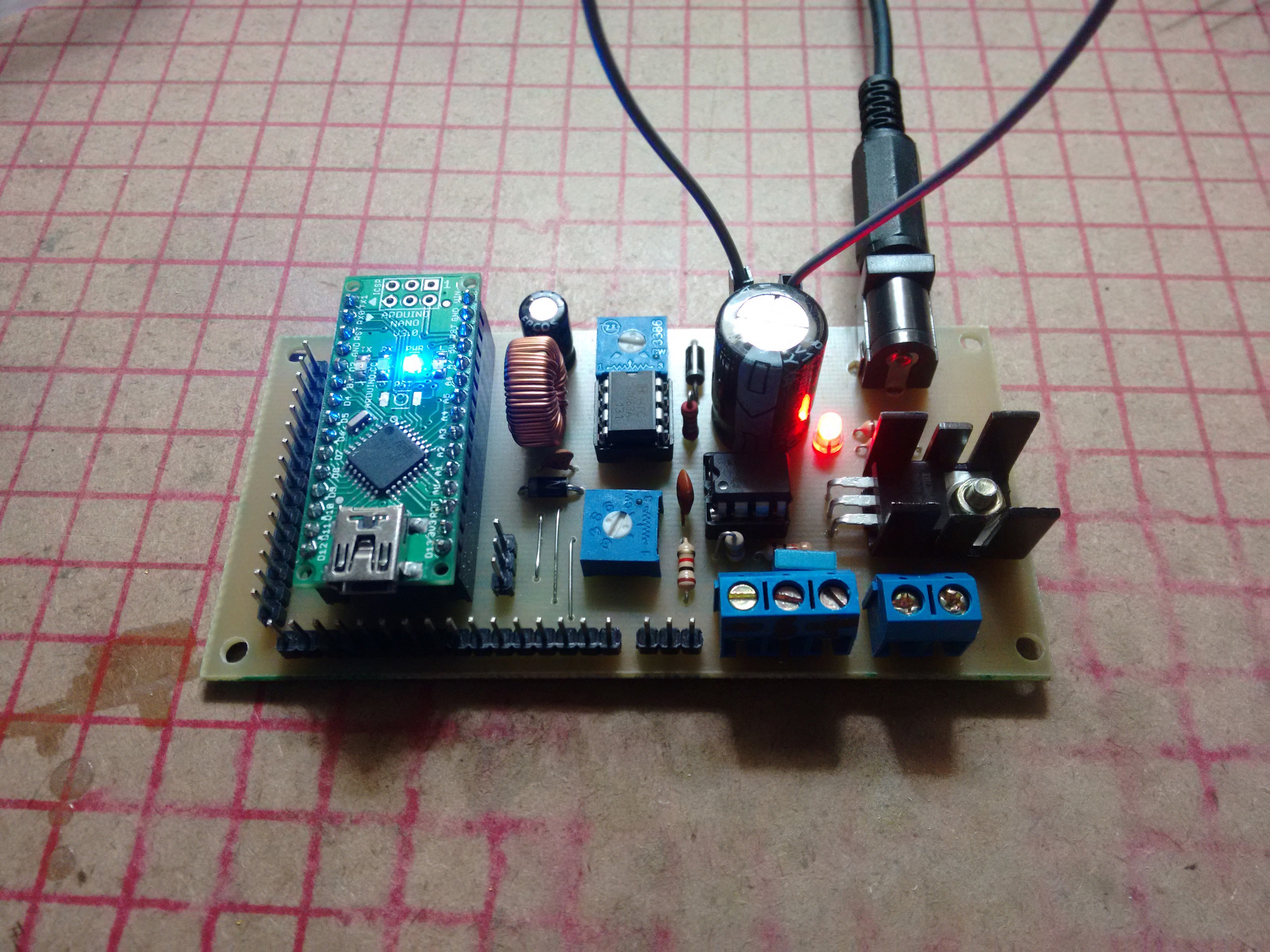 Everything seems to be working as expected. Next thing now is the program, but I'm rather tired after soldering the board.
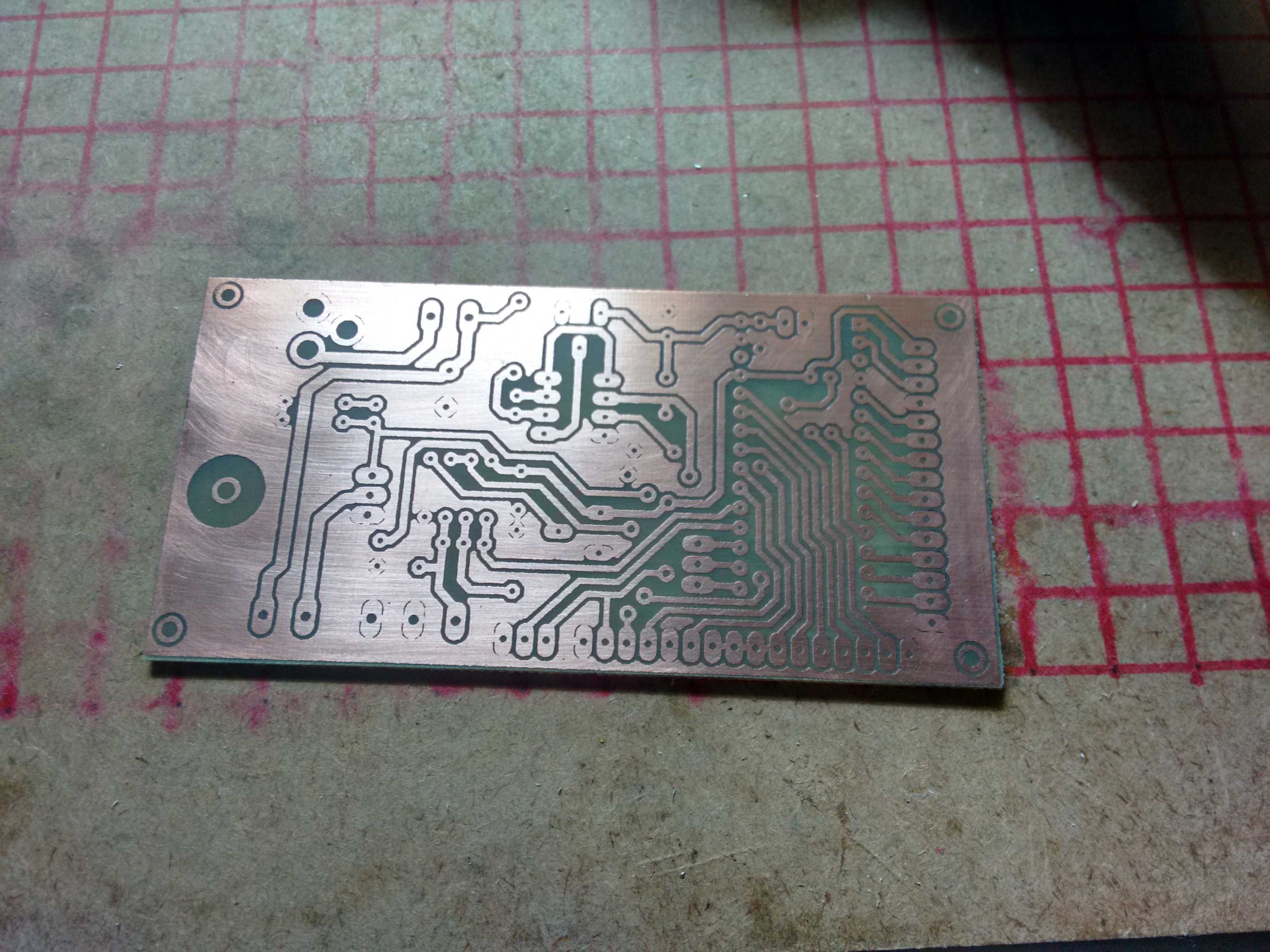 At home, I applied kind of a solder mask. It's actually a UV paint for purposes other than protecting PCBs.
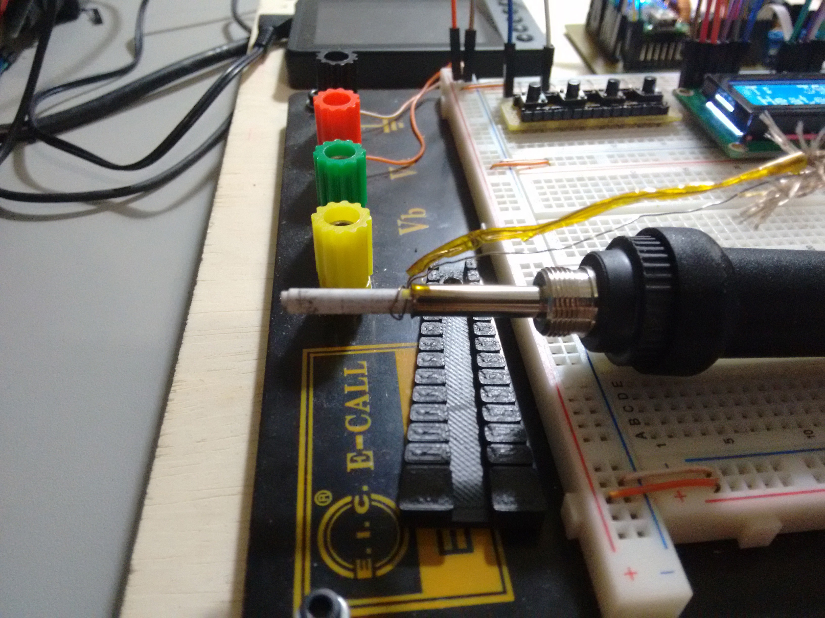
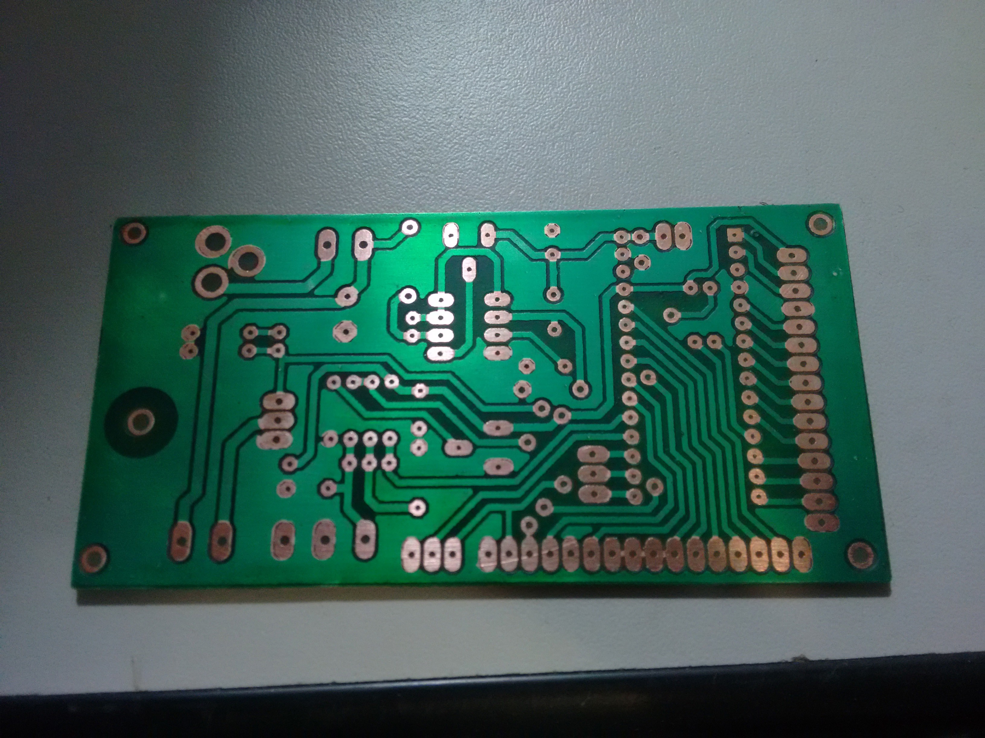 I have already drilled it, and will start assembling it soon.
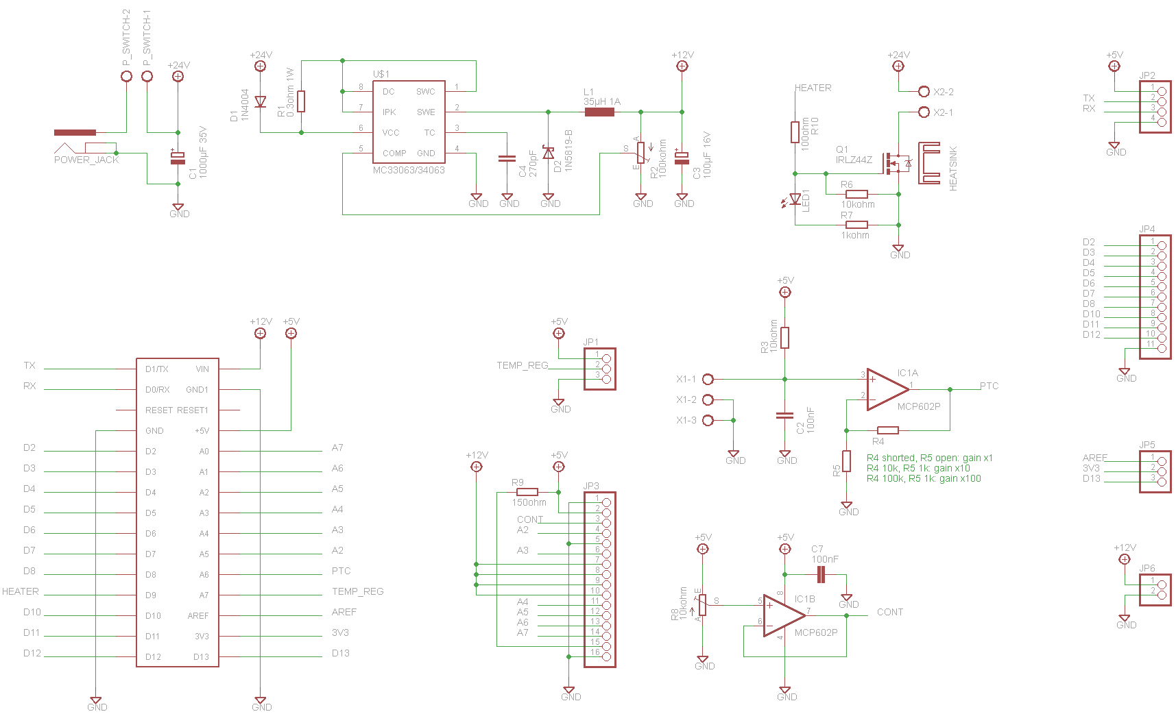


 David H. Bronke
 Andy
Andy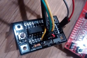
 lageos
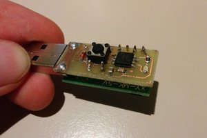
first of all I congratulate you on the project ...
I need advice from you ... I made the wiring as you exposed, I loaded the software as you gave it
... but all it displays are just the squares on the screen ...
I use arduino nano V.3 ... display 1602A ... and instead of irlz44z ... irfz48N ...
24V / 6A power supply
Do you have any idea what it would be like?
in the future if the problems are solved I want to replace the irlz44z ... with MOC 3021 and
BTA16 600 ... so I can use hot air .. I hope it will work ...