 Sebastian Lenartowicz
So I got this crazy notion into my head that I'll build a 3D printer from scrap parts. Well, that's great, but what next?
I started by collecting some scrap from my university's junk pile. They throw out a ton of e-waste, both functional and not, and I pulled out some components that might form a decent base for a scrapyard 3D printer.
My current design premise is based loosely on the RepRap Mendel, with XZ being paired and Y on its own.
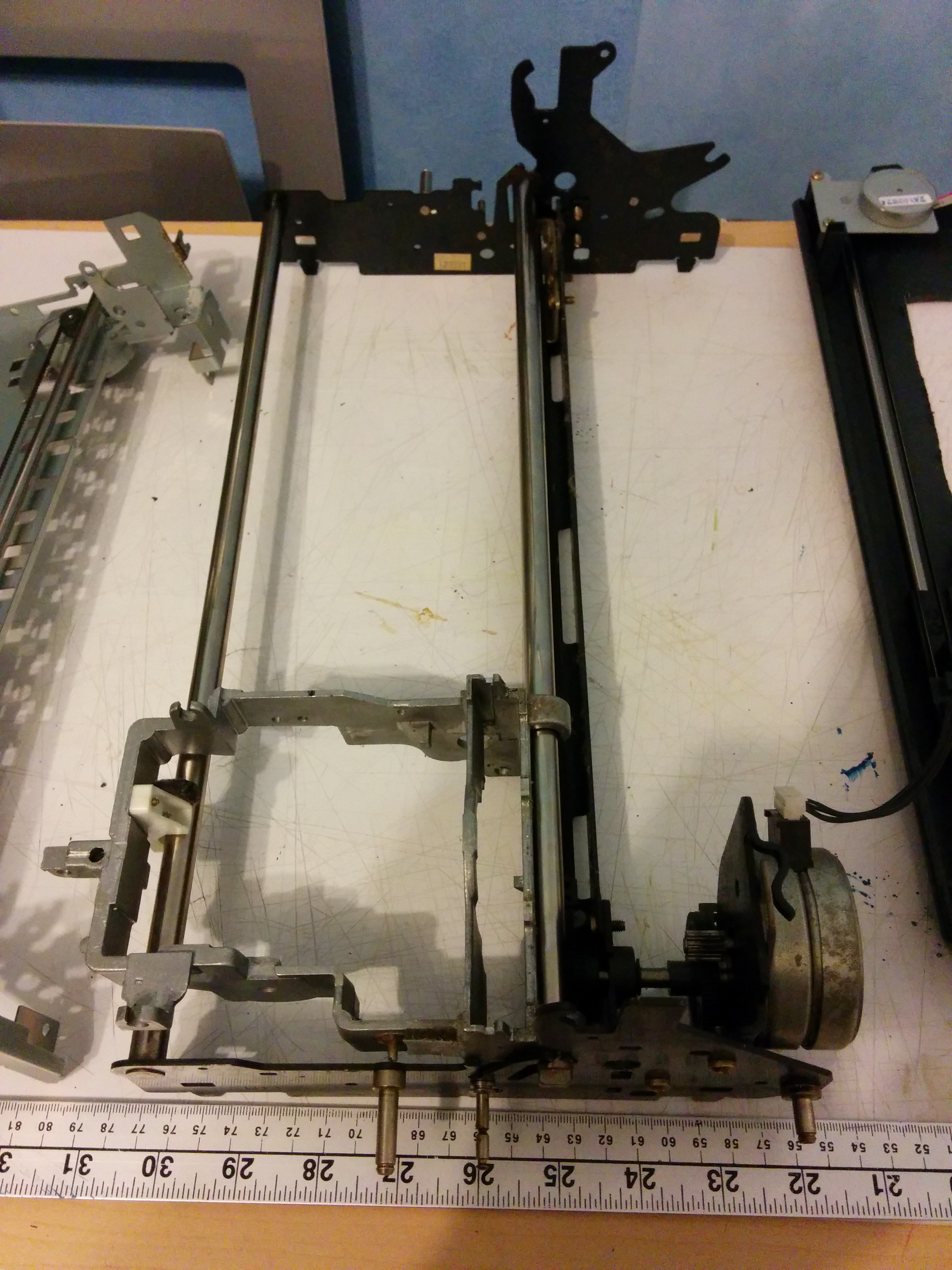
For the Z axis, I'm using this large carriage (left), salvaged from a (non-functional) IBM Wheelwriter electronic typewriter. It's more robustly built than either of my other two carriages, and has a geartrain attached to the stepper with a nice high ratio, so even if (as I suspect) the stepper turns out to have a high angle/step, I shouldn't have too many issues. As a plus, it's also got a nice long travel distance. The metal frame is very stiff, and the two rods should ensure that it moves smoothly and stays straight, even when it's loaded down with the X-axis components.
The X axis takes a similar tack, but this time it's the carriage off an inkjet fax machine (right), and it's a lot lighter than the massive typewriter components. 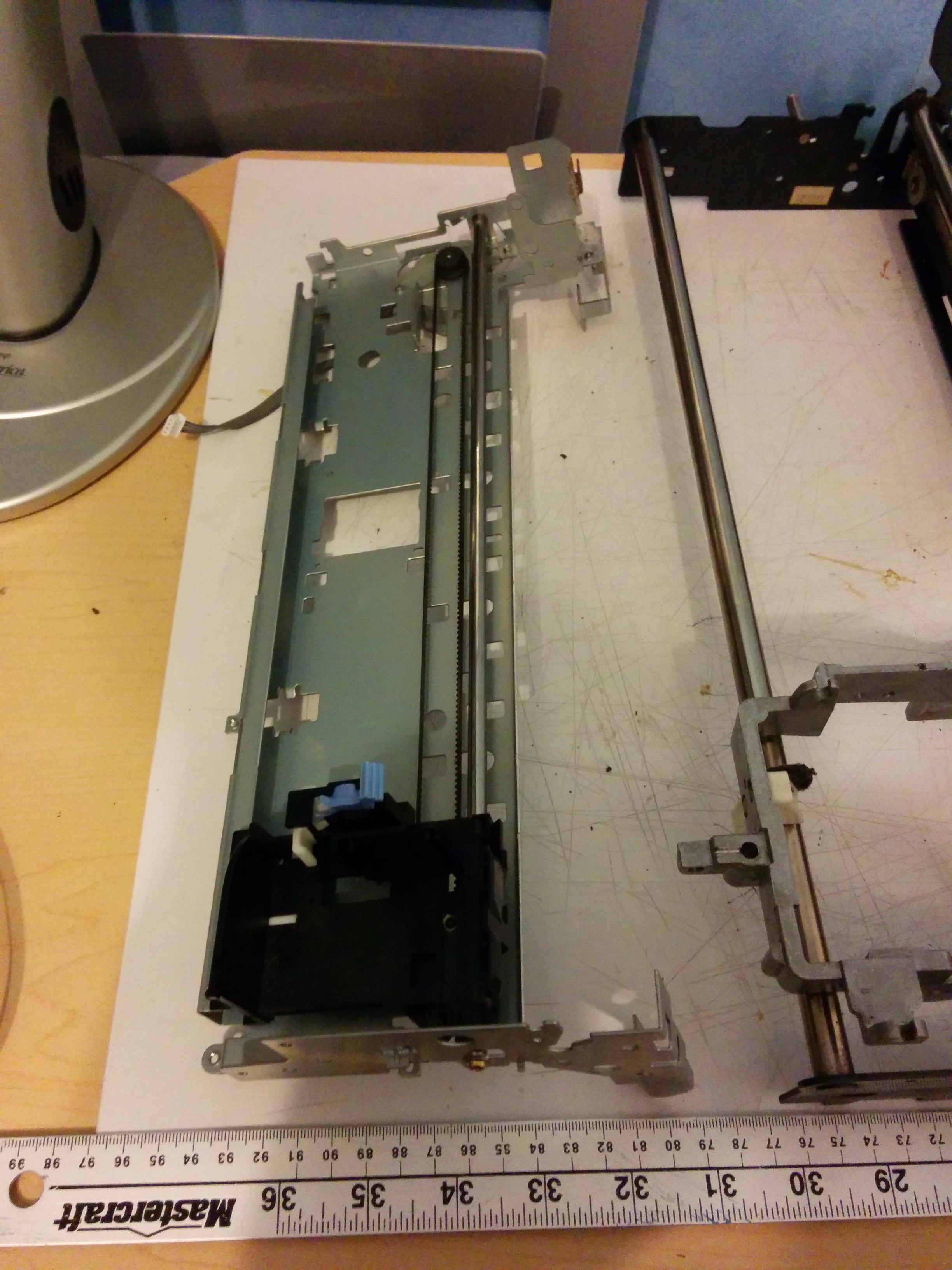 It has a shorter travel distance than the Z or Y axes, but I figure the light weight is worth the tradeoff. My one possible concern is that the datasheet for the stepper lists it as having an angle change of 7.5 degrees/step, though whether that will be an issue remains to be seen.
Both the typewriter and the fax machine carriage components will need some modification before I can use them to build the printer (mostly cutting away unnecessary protruding elements), but I will be keeping their basic structures intact because they are relatively stiff and strong.
Finally,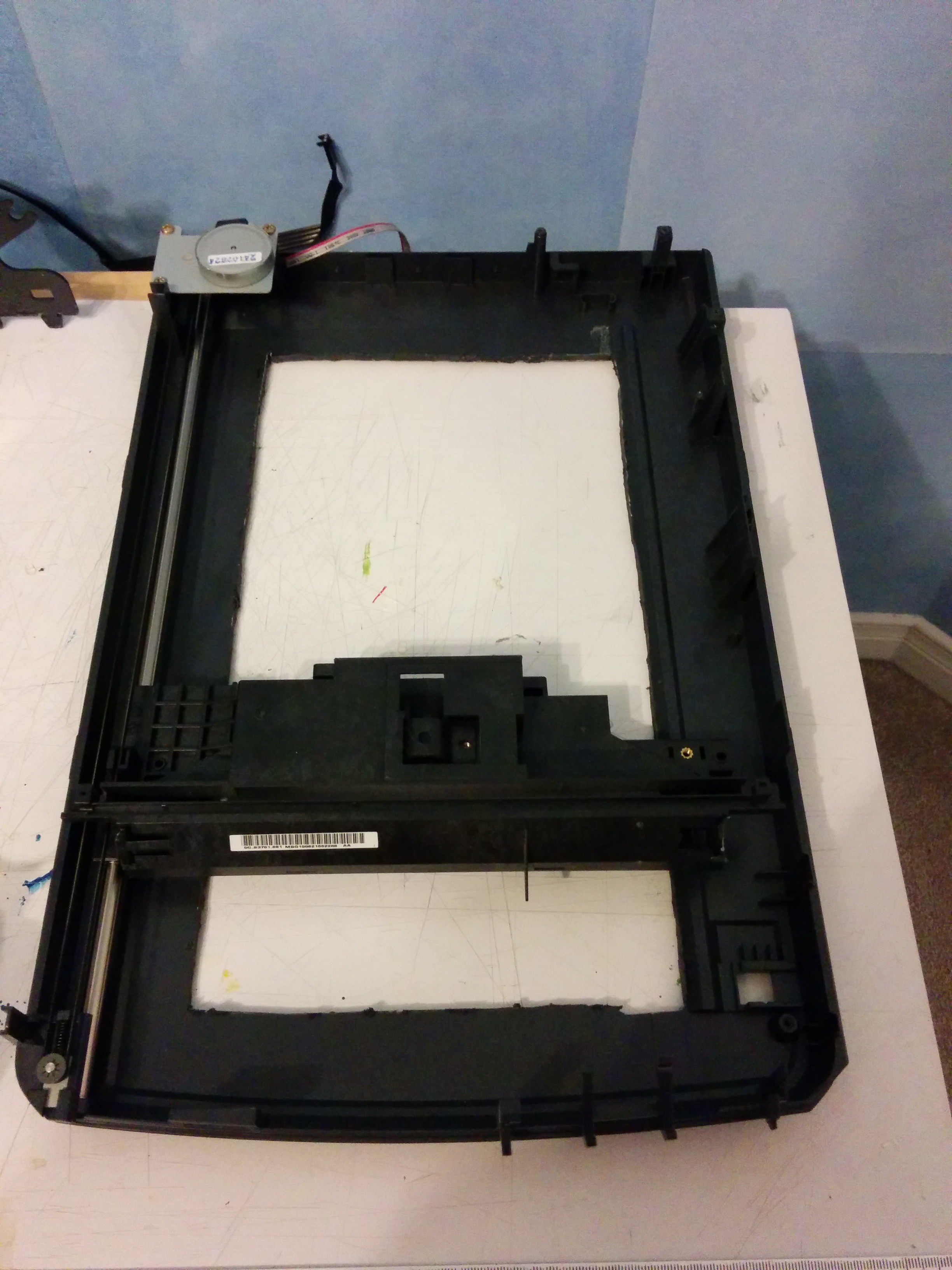 the Y-axis will be built from this: a dismantled Epson flatbed scanner (left). This model has a high maximum scan resolution, which leads me to believe that the stepper will be relatively precise. The current idea is to use brackets and bolts to mount the bed to the scan head (which has been completely dismantled, with only the plastic housing left behind). The scan head itself runs using a stepper and timing belt on one side (left in the picture) and a small wheel on a raised plastic ridge on the other. Whether the motor will be able to hold up to the rigors of 3D printing remains to be seen. And, yes, that is a hole in the bottom, cut when my design idea was for an XYZ-together printer (I was going to mount the extruder on the scan head). Now I figure it'll save some weight and make it a bit easier to see what I'm working on when I'm building it.
Discussions
Become a Hackaday.io Member
Create an account to leave a comment. Already have an account? Log In.