Close
0%
0%

Web powered antique wind gauge

An antique volt meter paired with a Raspberry Pi to display real time wind data.

Similar projects worth following
I do a lot of wind sports. Windsurfing, Kitesurfing etc etc. One of the sites I visit very frequently is the local weather station parked out in the sea. It provides a stream of real time wind data so I can decide if I need to drop what I'm doing and go and play with my toys.

So, to automate the checking, I'm attempting to pair up an old antique volt meter with a Raspberry Pi scraping the data from the website. The gauge is installed above my desk so I will know the moment it's windy enough for some fun times.

The aim then is to get the windspeed in knots and move the needle on the gauge to the right position. The obvious scale will be 1:10 so a reading of 50 Volts would indicate 5 Knots. Total range then would be 0-25 Knots. Things for me get interesting beyond about 15 so this is a pretty perfect range.

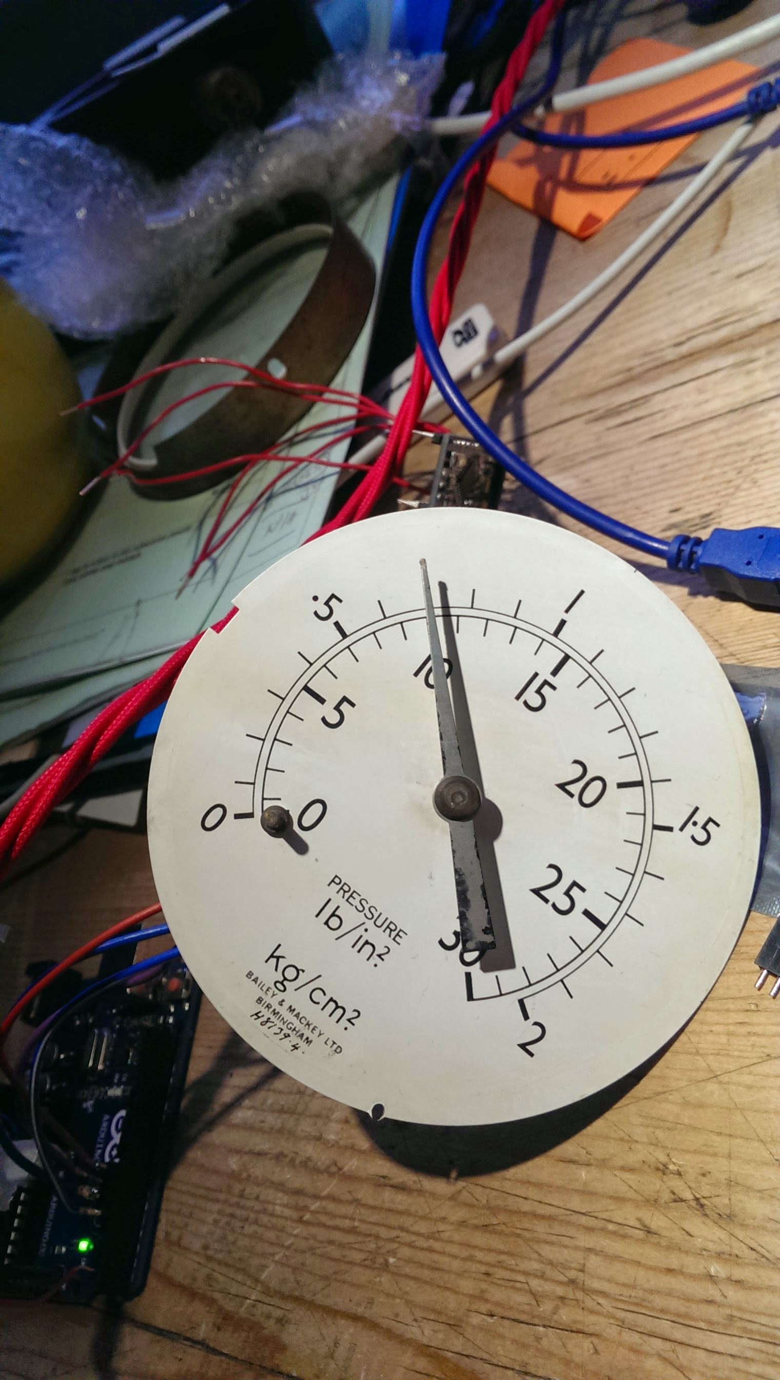
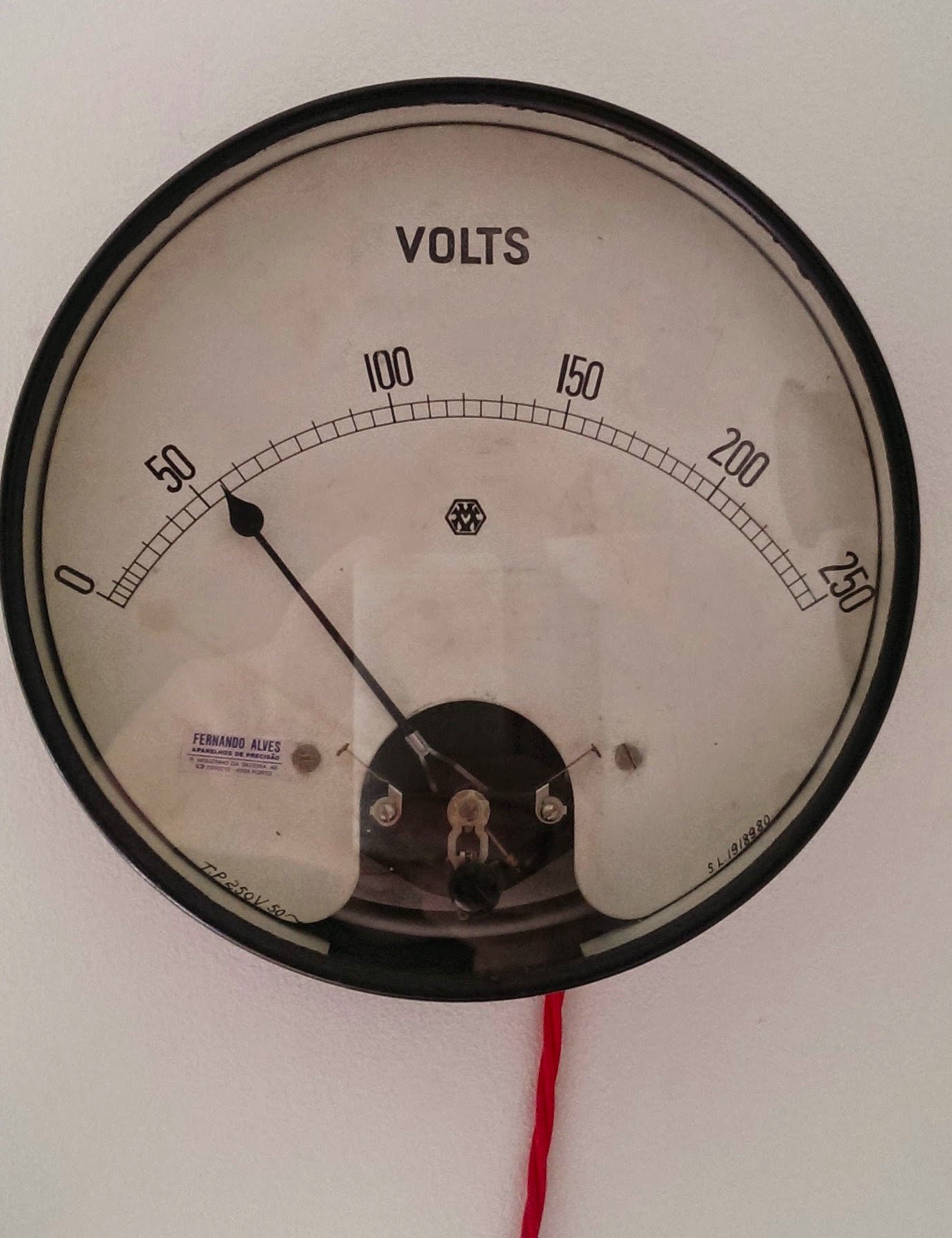
So why a gauge? Why not a 7 segment display or an LCD?

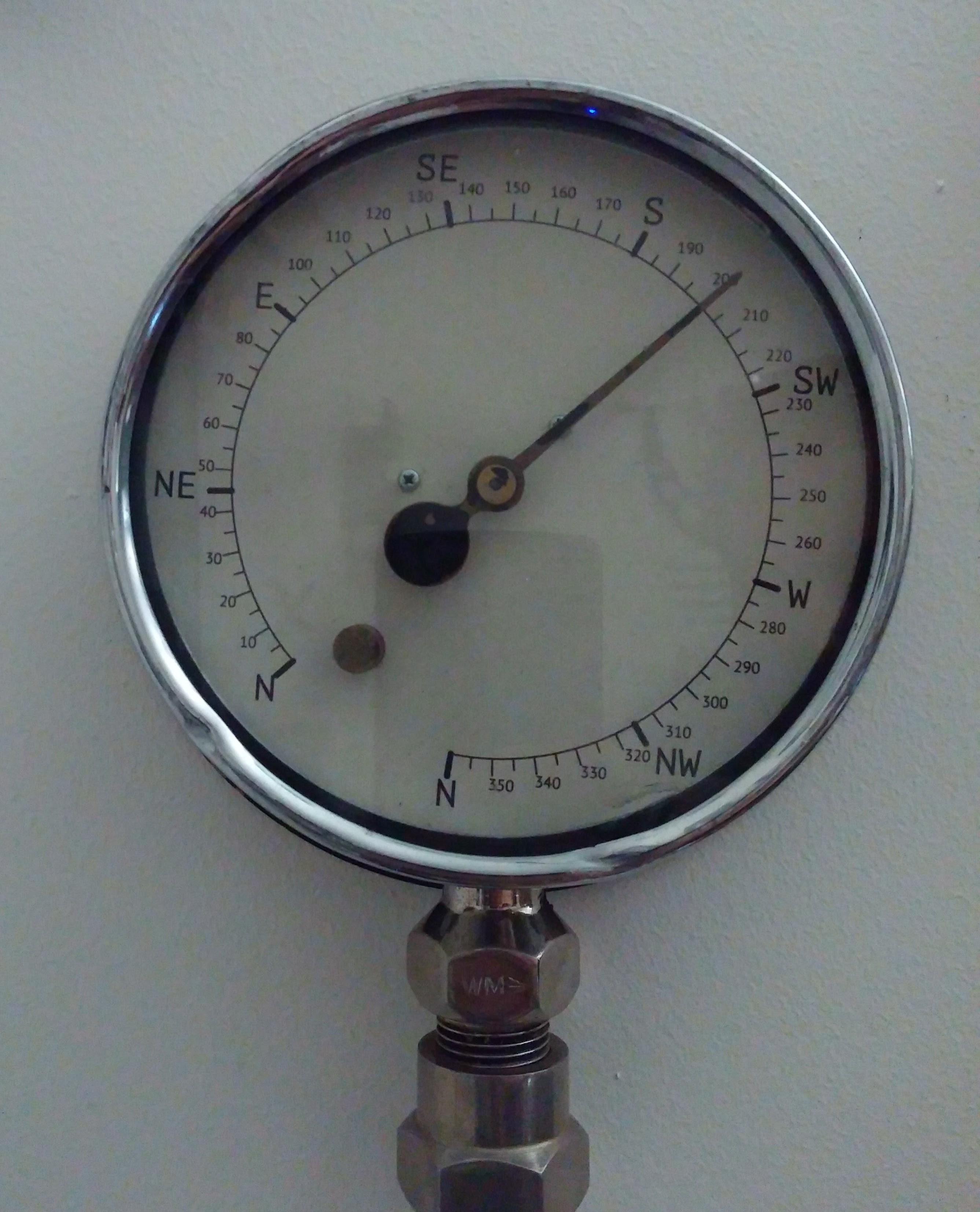
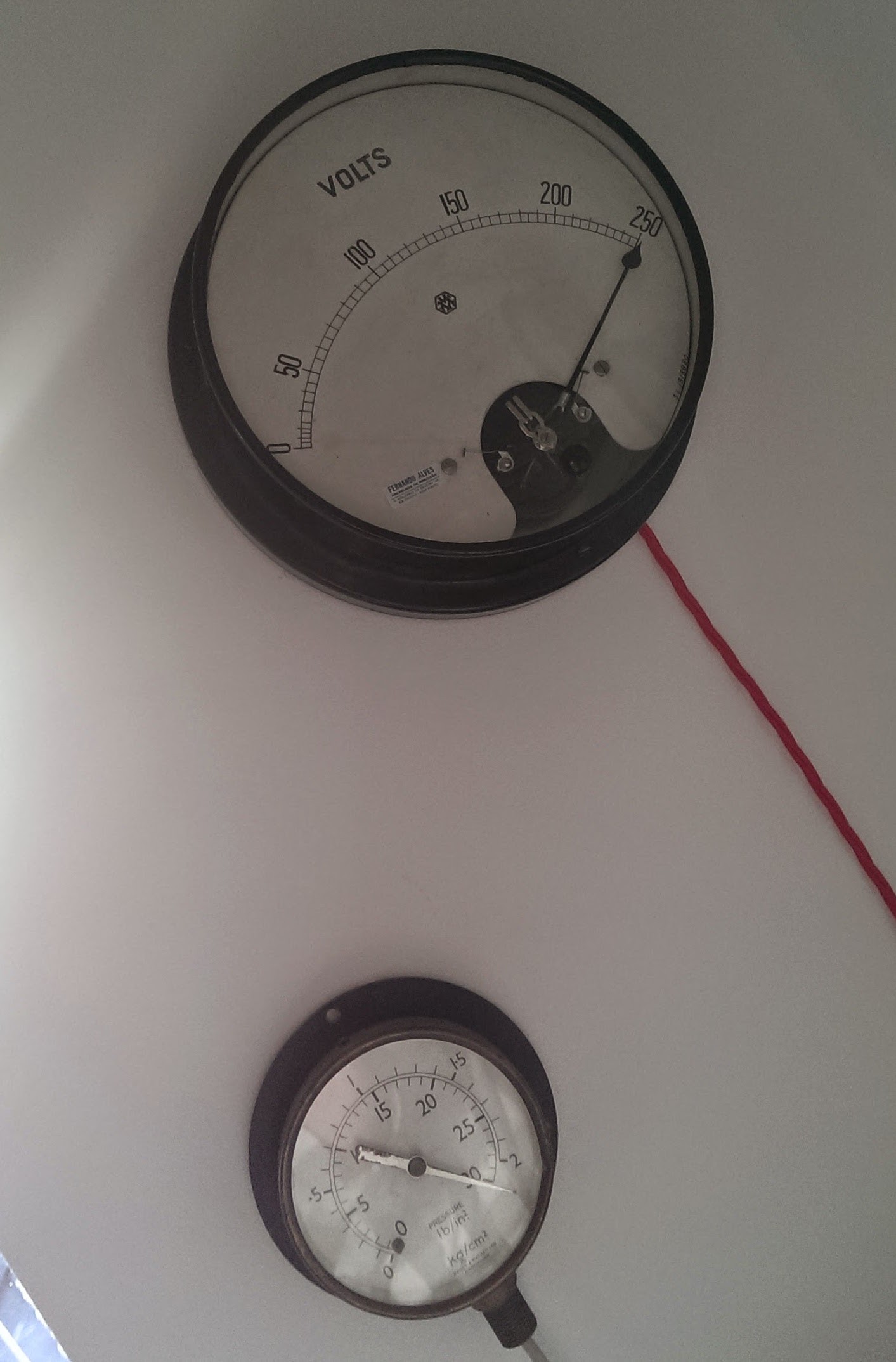
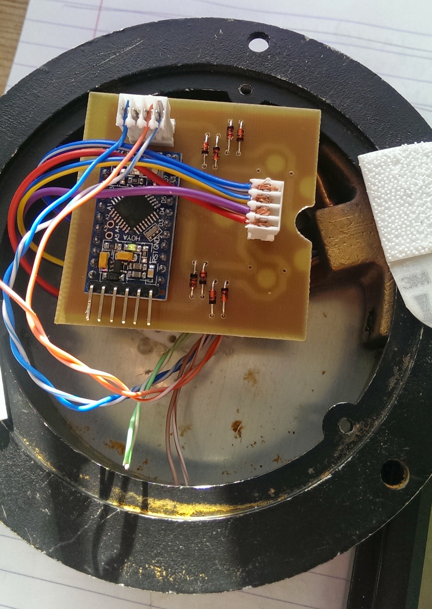
Well, I'm a scraped knuckles, oily fingernails kind of engineer normally. I deal with enormous bits of machinery, so I get a bit excited by old engineering tools and bits of old plant. It probably helps that I have a mild Steampunk obsession too.

As a consequence, I have weird bits of engineering paraphernalia in my flat as decoration. Part of that, is a collection of fairly antique gauges.

So 7 seg displays - boring. Antique volt meter steampunk style - Pretty Freaking Awesome!

  • A third gauge

    mechanicalsquid01/13/2016 at 20:12 0 comments

    The two wind gauges have been running for about a year now, and I'm really please with how well they work.

    As I've had a bit of spare time, I've added another gauge - wind direction. It works exactly the same as the other two, just set with a different identifying character for the serial data.

    The face had faded beyond what was legible so I took the opportunity to print up a new one with the points of a compass on it. Shame it can't go round in a circle, but it still looks great!

    I'm happy where this is now, so I'm going to mark this project as complete.

  • Two gauges...

    mechanicalsquid04/01/2015 at 06:02 0 comments

    I'd like, eventually, to have several gauges showing different useful items of information. Given that I've got two working, it makes sense to use them both. Average wind speed and maximum gust will work nicely for the moment.

    Some changes in the code are necessary. To drive multiple gauges from one serial line we end up with a master/multiple-slave type situation. There are various protocols that would be good for this: RS485 is the one I'm most familiar with, but I2C would work too. Before I go down that road though, I'm of the opinion that simplest=best so I'm going to try sticking with just using the TX pin from the Pi and dividing it between multiple 'slaves'.

    So, I need some new arduino code. I'm going to use a single identifier character to indicate which gauge the message is for. As before, a new line indicates message complete. I'm also going to add a character to 'reset' or zero the gauges.

    It's getting a bit long to be posting the code up here, so I signed up for Github.

    They work! Hurrah! And yes, it's extraordinarily windy today.

  • PCB testing

    mechanicalsquid03/31/2015 at 17:16 0 comments

    Despite my best efforts, I couldn't get a PCB made at my makerspace. However, I asked one of the guys in the electronics workshop at my university and he was very happy to help out. And this is what he produced:

    So I fired up the soldering iron and put it all together:

    I managed to program the Arduino Pro Mini with instructions from from here. Really very straight forward. Once programmed, I tried it out on my small gauge:

    Worked first time! Well chuffed.

  • PCB making

    mechanicalsquid03/31/2015 at 16:31 0 comments

    It's been a little while. Master's degrees are hard work - who'd have thought!

    Anyway...in anticipation of tidying everything up a bit, I designed a PCB. I've never done this before, so the learning curve was steep. An Arduino Pro Mini does the brains, and pads for directly soldering on a stepper, or for a connector for a remote mounted stepper. An identical connector takes the cables to the PI. I also added some diodes for flyback protection. This is what it looks like:

    So off to my local makerspace (somakeit) to have a crack at making it.

  • Driving the big gauge with steppers

    mechanicalsquid01/29/2015 at 07:53 0 comments

    Attaching a stepper to the big gauge is a bit more of a challenge. I'm pretty keen on maintaining the original appearance of the gauge, so from the front it needs to appear unmodified, but there isn't a lot of room in the back for the motor.

    Here's how it looks in bits:

    Some modification is necessary - I cut off the back (well, more snapped off really...) support for the rear bearing which makes just enough room for the motor. I cut down the needle shaft so the motor would fit in the back and then pushed a bit of wire insulation over the shafts to join them together. I also removed the return spring and damper - these aren't used any more and were just getting in the way.

    Read more »

  • The arrival of the steppers

    mechanicalsquid01/26/2015 at 15:00 0 comments

    I've finally had a few hours to play with the Switec steppers.

    They're pretty cool little things. Guy Carpenter has published an Arduino library for driving them. They only pull 30mA/coil so can be driven directly from the Arduino. For a permanent solution though, some protection diodes should probably be thrown in.

    As a first test, I deconstructed one of my other gauges and stuck one of the steppers on the back of the face. A bit of tweaking and a bit of superglue and I have it all stuck together nicely.

    Loading up an Uno with Guy's example script, fiddled around getting the right wires connected to the right pins and it works very well. As you'd expect with a stepper, repeatability is perfect.

  • Servos aren't accurate

    mechanicalsquid01/05/2015 at 09:50 0 comments

    It's been running in this configuration for a little while now. It works well, but the inaccuracy of the servo is just terrible. It seems pretty random how much overshoot there is so the unpredictability is difficult to manage in software.

    Options to improve this are:

    1) Try a better servo ($$)
    2) Move encoder to the needle and add a control loop
    3) Use a stepper motor.

    Really good servos are expensive, and from my research, I'm not convinced they'll have the necessary accuracy. Adding an encoder to the needle could be done - either the one from inside the servo and use the servo's control loop, or add another one around the whole thing. Possible, but I think this is a bit messy.

    So, going for option 3). I'm going to use the Switek X27.168 steppers designed for car gauges (Thanks to Adam for pointing these out in the comments).

    Somehow, I need to physically connect the shaft to the needle. Not sure how to do this yet.

    Also, someone parked a ship in front of the weather station I was using for data. It's still working, but unsurprisingly, the ship affects the reported windspeed somewhat. Given how hard it's gone aground I think it'll take a few weeks to move it.http://www.bbc.co.uk/news/uk-england-hampshire-30677320

  • Custard Pi, Python and Servos

    mechanicalsquid12/02/2014 at 09:04 0 comments

    The cable, and the Custard Pi turned up.

    First, I'm trying the servo on an external power supply. I'll try it from the Pi later, but as I already know it works from an external supply, I want to change the minimum possible.

    With the servo signal pin connected to GPIO 22 (pin number 15 on the Custard Pi), a short python script to verify it moves:
    import timefrom RPIO import PWM
    
    lookup=(600,640,680,720,760,800,850,900,950,1000,1050,1090,1130,1170,1210,1250,1310,1370,1430,1490,1550,1660,1770,1880,1990,2100)
    while True:
        for windspeed in range (0,6):
            print("Servo position: "+ str(lookup[windspeed]))
                    servo=PWM.Servo()
            servo.set_servo(22,lookup[windspeed*5])
            time.sleep(1)
    You'll notice I'm using a lookup. This is to account for the non-linearity in the resistor linkage. While I'm sure there's a mathematical technique to compute the equations of motion - there's only 25 positions. A lookup technique is far easier.

    The script moves the pointer from 0 to 5, 10, 15, 20 and 25 before returning to 0. And it does.

    But, the accuracy and repeatability of the servo is really pretty shocking. It never gets to quite the same position twice and always overshoots by as much as two ticks depending on the starting position.

    While two ticks isn't really that big a deal - it equates to two knots, it's going to irk me somewhat, so I'll have to come up with something. Adam, in the comments has already pointed me at stepper motors designed for driving gauges. And I'm also told that digital servos are much better - this one is after all the cheapest I could get my hands on.

    While I'm considering that though, there's no reason why I can't take my windspeed script of earlier and use it to drive my inaccurate servo:

    from bs4 import BeautifulSoup
    import requests
    import time
    from RPIO import PWM
    
    lookup=(600,640,680,720,760,800,850,900,950,1000,1050,1090,1130,1170,1210,1250,1310,1370,1430,1490,1550,1660,1770,1880,1990,2100)
    
    r=requests.get("http://www.bramblemet.co.uk/wap/")
    data=r.text
    soup=BeautifulSoup(data)
    link=soup.find('a')
    p=requests.get(r.url[:-18]+link.get('href'))
    windpage=p.text
    soup=BeautifulSoup(windpage)
    windspeed=int(soup.prettify()[309:315])
    
    if windspeed>25:
        windspeed=25
    if windspeed<0:
        windspeed=0
    
    print("Servo position: "+ str(lookup[windspeed]))
    
    servo=PWM.Servo()
    servo.set_servo(22,lookup[windspeed])
    time.sleep(1)
    

    It works! Also I added a cron to update it every 10 minutes.

  • Pi connections

    mechanicalsquid11/27/2014 at 16:00 0 comments

    I'm intending on using the RPIO library to drive the servo from the Pi:

    https://pythonhosted.org/RPIO/pwm_py.html

    So I need to connect it to the GPIO pins somehow. I struggled a bit to find a breakout board that didn't just connect to a breadboard or a prototyping PCB. What I really wanted was something with screw terminals, which I finally found here:

    http://www.sf-innovations.co.uk/custard-pi-1.html

    One Custard Pi ordered. (My girlfriend thinks I'm trolling with these names, especially when I commented that probably the Custard Pi won't fit in the Raspberry Pi case)

    I also need some cable to run from the gauge to the Pi. Currently, the Pi sits under the desk just below the gauge. It also runs a NAS and OpenVPN along with a few other server related tasks, so moving it into the back of the gauge isn't an option.

    The cable needs to look the part too. It's coming out of an antique gauge, so I need something suitably steampunk and interesting.

    3 core fabric covered lighting cable should do it:

    http://www.ebay.co.uk/itm/271224071005?var=570170742412

  • The Servo

    mechanicalsquid11/27/2014 at 15:52 0 comments

    Wow this thing is cheap. I shouldn't be surprised, it was!

    First thing was to connect it up to an Arduino running the Servo Sweep example just to check it works. It does, but it's pretty noisy!

    In trying to connect it to the gauge, I'd been hoping that I could attach the needle to it directly. It seems that it's too big for this though. So I'll have to keep the needle on it's original bearings and drive with a linkage. Which I'm quite happy about as they're beautiful construction. Destroying them would be a shame.

    Offering up the servo and moving arms around suggested that the best place would be just on the side of the needle frame. Then a link to an arm on the needle shaft. Of course I need something to link the two - not having any rod lying around, a stray resistor was pressed into service.

    A dab of superglue to hold it all together, then connected back up to the Arduino to check servo/needle movement.

    Surprisingly, nothing bent or fell off! I had to adjust the linkage a bit to get the right ratios and range. I left it running for half an hour to check for security, and everything seems good.

    Now then, I need to run this from the Pi.

View all 14 project logs

Enjoy this project?

Share

Discussions

Eivol Ekdal wrote 01/05/2015 at 12:30 point

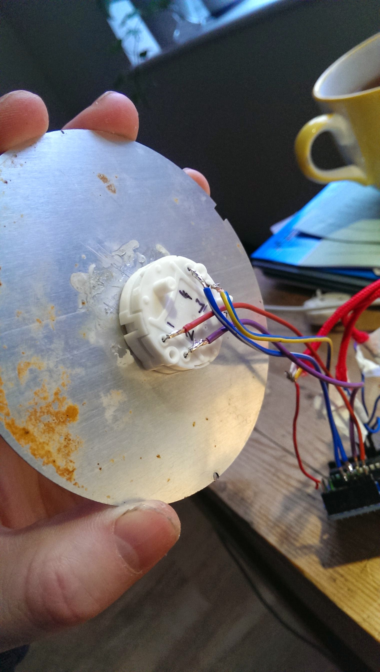
I have a working project that is similar using a 150 uA moving coil ammeter.
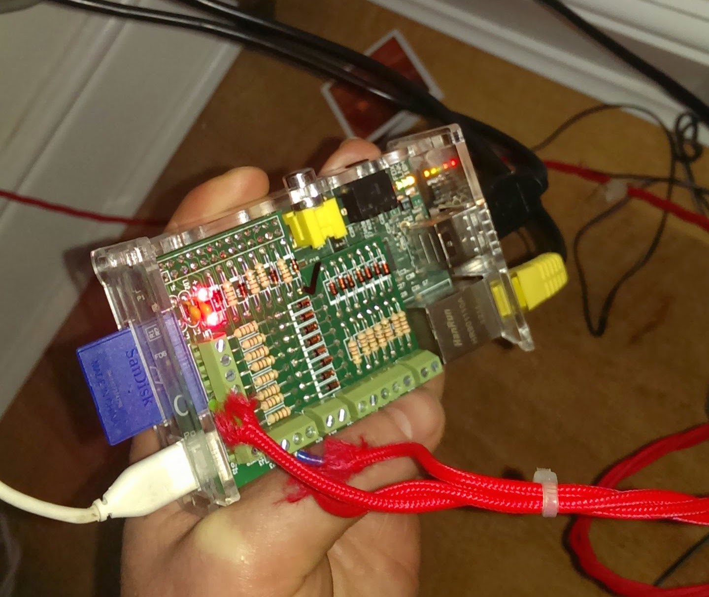
I have used the Adafruit MPC4725 DAC...

https://learn.adafruit.com/mcp4725-12-bit-dac-with-raspberry-pi

I have a 5K shunt resistor across the coil and the DAC outputs to the coil through a 10K trimpot.

The DAC is controlled by the Adafruit Python Library.
I use Feedparser to read a RSS feed.

https://pythonhosted.org/feedparser/

I write out the current comment count on a blog that has a Disqus comment system to a text file.

This script is called by cron every 5 minutes...

#!/usr/bin/python

from Adafruit_MCP4725 import MCP4725
import time
import feedparser
import os


#SineLookup Table
SineLookup = \
[ 178, 350, 512, 658, 784, 887,
962, 1008, 1024, 1008, 962, 887, 784, 658,
512, 350, 178, 0, -178, -350, -512, -658,
-784, -887, -962, -1008, -1024, -1008, -962, -887,
-784, -658, -512, -350, -178, 0 ]

# Initialise the DAC using the default address
dac = MCP4725(0x62)
#dac.setVoltage(0)


#get latest comment count

blog = 'tonyortega.org'
d = feedparser.parse('http://' + blog +'/feed/')
comments = int(d['entries'][0]['slash_comments'])
#scale value to meter - full scale = 1000
meter = int(float(4.095 * comments))

# Read previous comment count

with open("/home/pi/count.txt", "rt") as in_file:
text = in_file.read()

#get comment delta
sweep = (comments - int(text))

#play sound if new post.
if sweep < 0:
os.system("mpc -q play 1")


#sine sweep needle once for each new comment
while (sweep > 0):
for val in SineLookup:
dac.setVoltage (meter+(int(val)))
time.sleep(0.03)
sweep = sweep - 1

# Write latest comment count to file
dac.setVoltage(meter)
with open("/home/pi/count.txt", "wt") as out_file:
out_file.write (str(comments))


The above works quite reliably and the DAC holds it value between runs.

  Are you sure? yes | no

mechanicalsquid wrote 01/05/2015 at 12:34 point

Nice!

I do have some 50uA meters hanging around (because who doesn't? Right?) They don't look good though.

Although the though now occurs to me that I could perhaps rob the driving coil/magnets...

  Are you sure? yes | no

Eivol Ekdal wrote 01/05/2015 at 12:46 point

Early test vids...

https://vid.me/8y4

https://vid.me/8y4

My meter movement has had all the dampening removed for some insane
reason....

http://www.allelectronics.com/make-a-store/item/pmd-100u/6-precision-125-dc-ua-meter-used/1.html

So the script I posted above has delays built in to slow things down.

  Are you sure? yes | no

mechanicalsquid wrote 01/05/2015 at 13:52 point

Very nice indeed. Have you considered software damping? Ramp to a value in progressively smaller steps to counter the bounce?

  Are you sure? yes | no

Eivol Ekdal wrote 01/05/2015 at 21:26 point

I have considered it but not really that bothered. With the delays I have been able to dial in how fast to move the meter before it gets too carried away. The blog comment count rises slowly during the day so I put in function to 'wag' the needle once for every new comment. Besides, the bounce is a unique feature of this panel meter that I would like to preserve. Google "e-meter"
If I was using it for a VU meter I would go with a properly dampened movement.

  Are you sure? yes | no

Adam Fabio wrote 11/30/2014 at 07:53 point
One thing with servos - they don't last for very many hours in continuous use. You might want to check out stepper motors - The switec X27.168 and similar motors were originally used to drive gauges in ford and GM cars. You can get them on ebay for 3 or 4 dollars. Here's a library to get you started: https://github.com/clearwater/SwitecX25
(Disclaimer - I designed and sell a breakout board kit for these motors)

  Are you sure? yes | no

mechanicalsquid wrote 11/30/2014 at 13:04 point
Thanks Adam.

I'm a little further ahead than this blog would suggest. The servo is actually only being driven for 1 second every 10 mins, although I've hit a snag. The accuracy and repeatability is pretty shocking. A stepper motor would be the answer.

I didn't realise they came nicely packaged up like that. I'll definitely be exploring that route.

James.

  Are you sure? yes | no

Similar Projects

Does this project spark your interest?

Become a member to follow this project and never miss any updates