 RasmusB
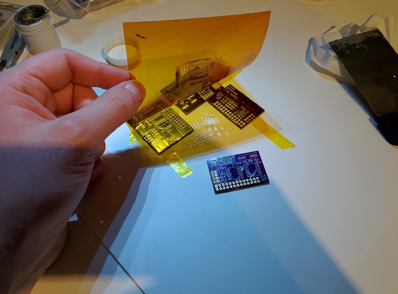
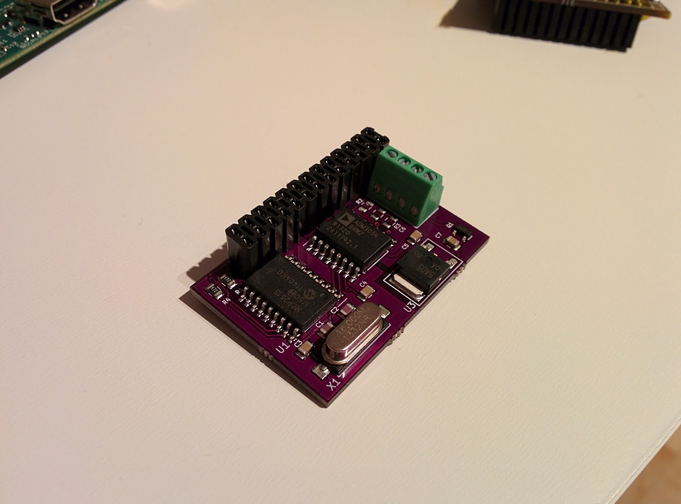
Here you'll find the hardware design files for a CAN controller for the Raspberry Pi SBC.
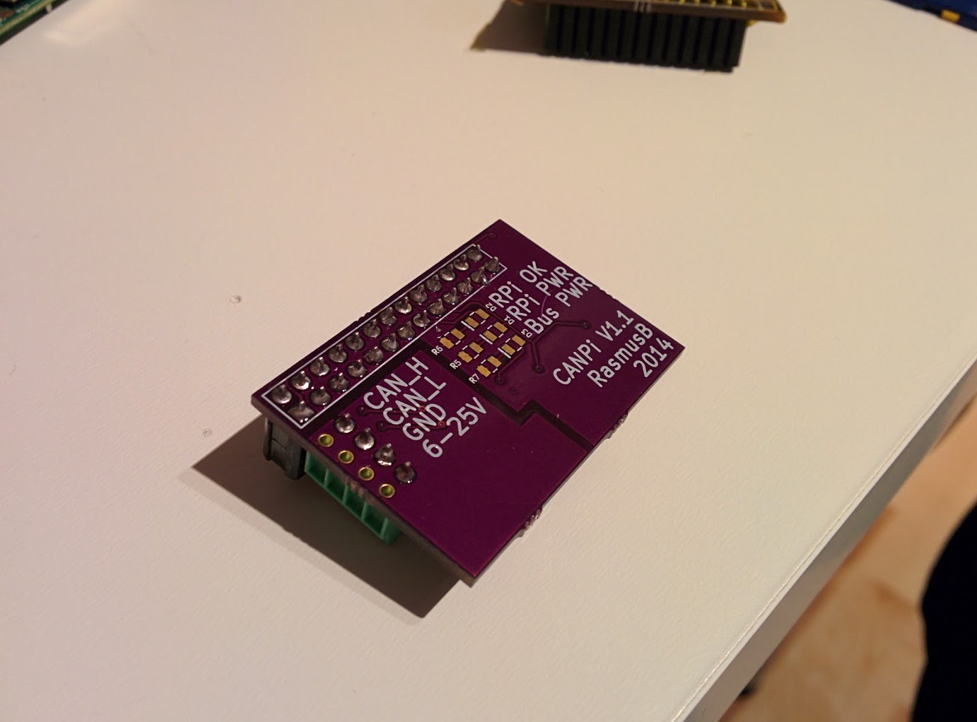
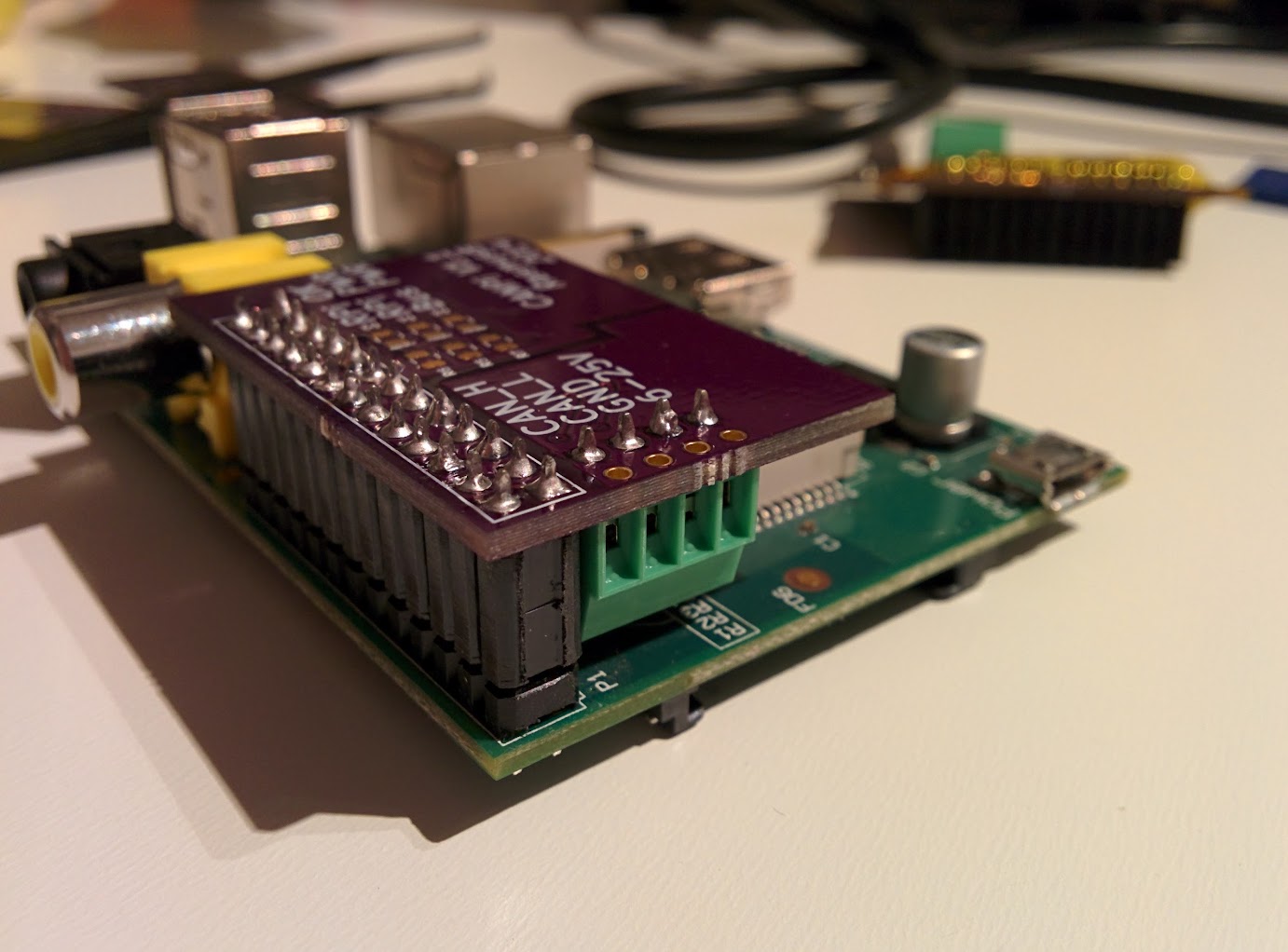
It is designed to be easy to use. The CAN transceiver keeps the RPi and the CANPi elctrically isolated, so you do not need to worry about voltage levels. All you need to do is connect the CAN signals and a voltage supply @ 6-25V DC, which usually can be shared with the device you want to communicate with. The power input is reverse polarity protected.
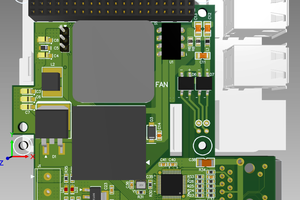
Note that while the CAN transceiver is rated for up to 5000V isolation, the board layout most definitely is not! Voltages up to 25V is no problem though.
If you just want the PCB, it can be ordered from here: http://oshpark.com/shared_projects/20v7dQka
How do I use it?
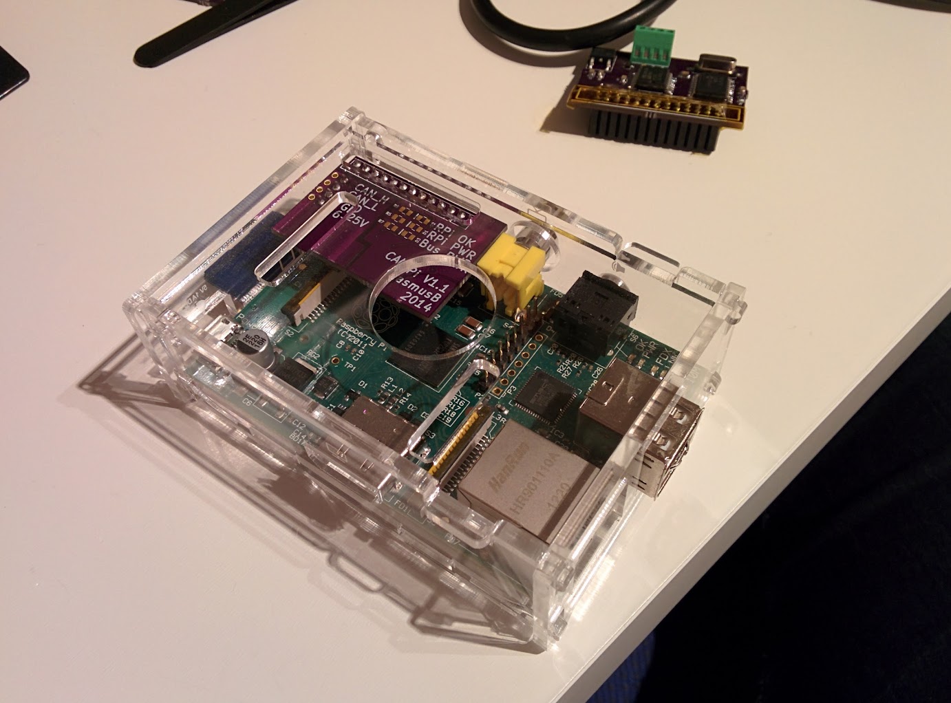
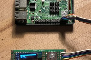
When your Raspberry Pi has been properly setup, you will have access to a /dev/canX interface. Through the magic of socketcan, this works a lot like a network interface.
Follow these instructions to configure your RPi: http://lnxpps.de/rpie/ . The hardware used in those instructions is a bit different, but the CAN controller and the interface to the RPi is the same so there is no difference in practice.


 Poyu Chen
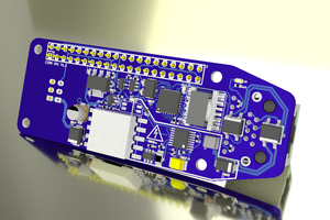
 julien
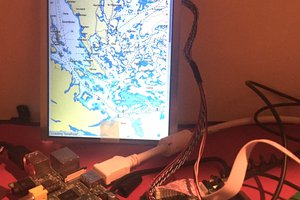
 Alan
Alan
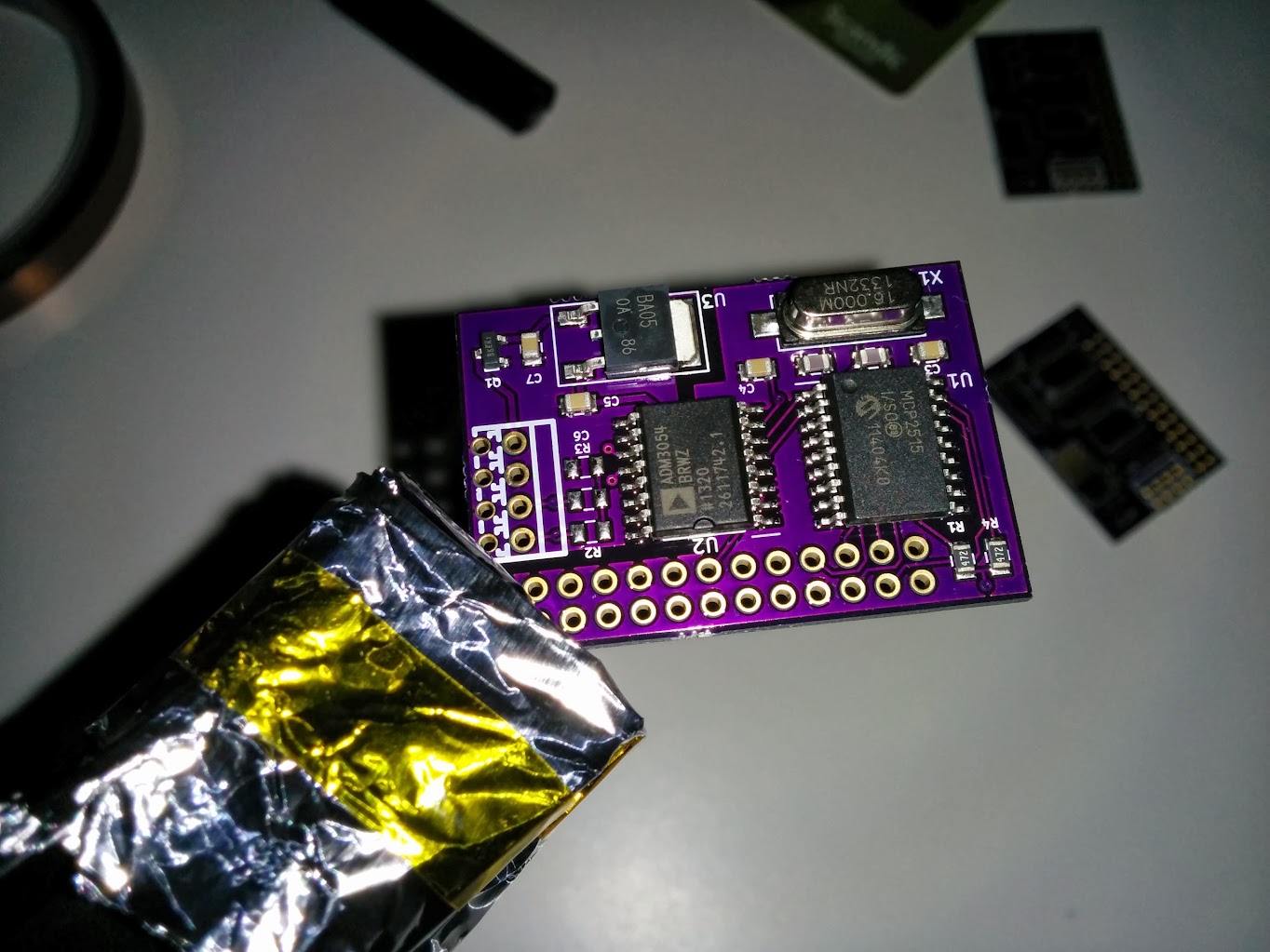
Why did you pick a series resonant crystal (which the ATS160SM-1 is as per manufacturer's datasheet) instead of parallel resonant?? The configuration is clearly parallel, given how you have the loading capacitors tied. And, the MCP2515 needs parallel resonant -- in fact, the MCP2515 datasheets specifically says not to use series resonant part as it will cause the frequency to be out-of-spec (see 8.0 in the datasheet).
Was this a part's specification/selection error? Or did you intentionally pick a series resonant crystal for a reason?