Hacker404
This is an old old project that was put on the back burner (in the shed) for years.
I don't remember when I bought it or if it was working at the time.
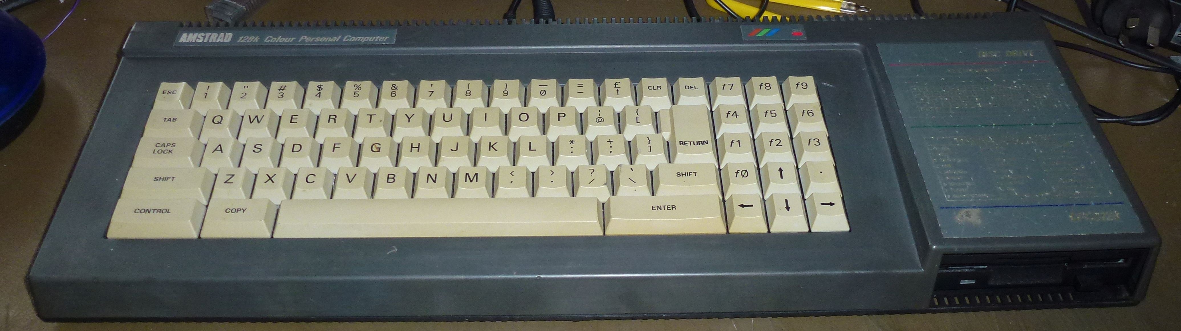
This computer was intended to work with monitor that was originally bought with the computer and the power supply was built into the monitor. I don't have this monitor.
I just plugged a 5 Volt power supply into the back of it and ignored the 12 Volt input as I know that is only used for the (3 inch) floppy drive.
As it had a monochrome composite (sync) output, I connected that to a TV and this is what I got.
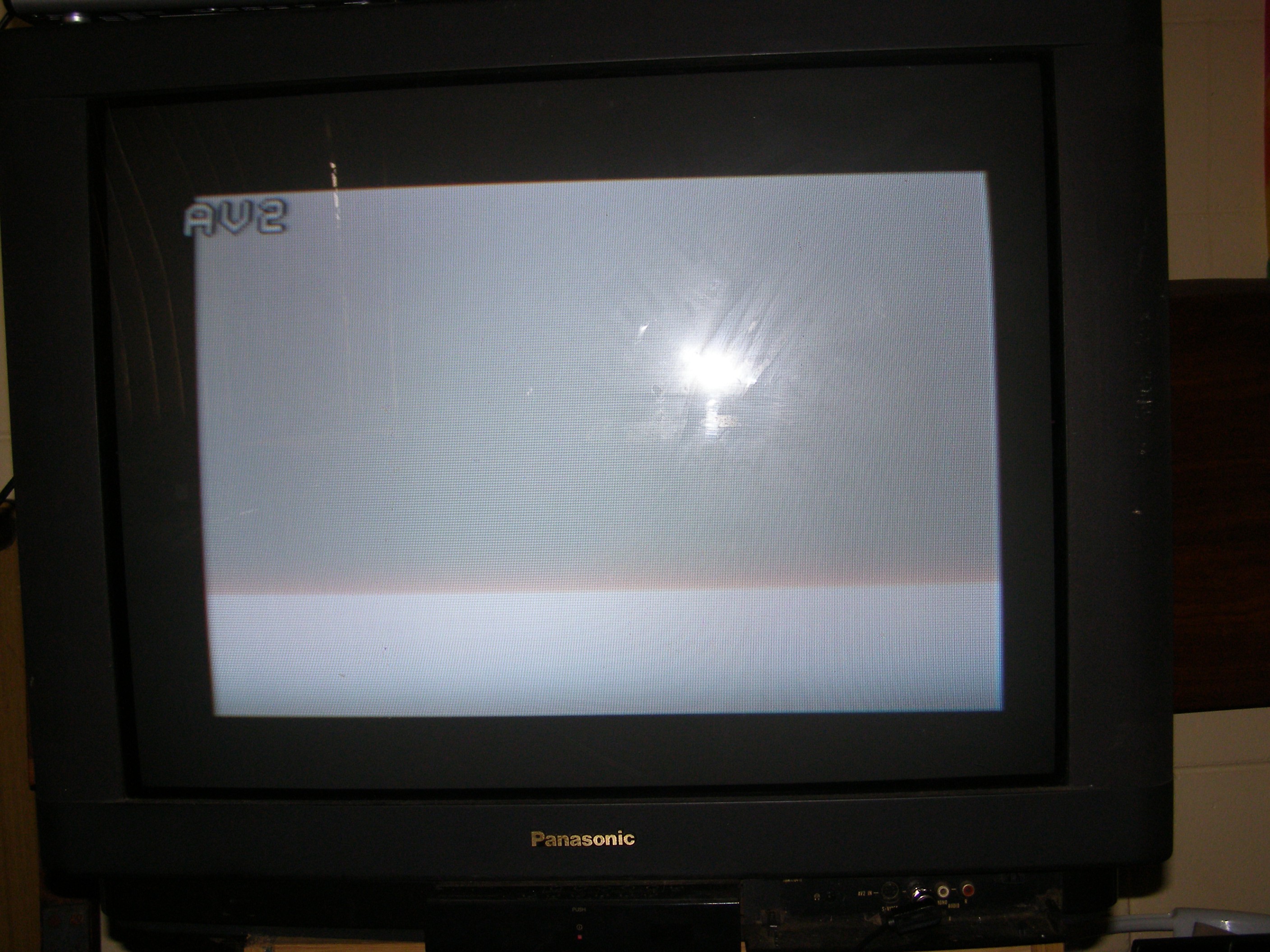
The white area is where the normal screen goes but it should be yellow text on a blue background.
Although disappointing, this did give me some clues. The CPU and CRT controller chips were working as I have video sync, the active area drawn and the co-responding RAM has been blanked by the CPU otherwise I would have a random pixel pattern instead of a white block.
Time to see what's in the box ...
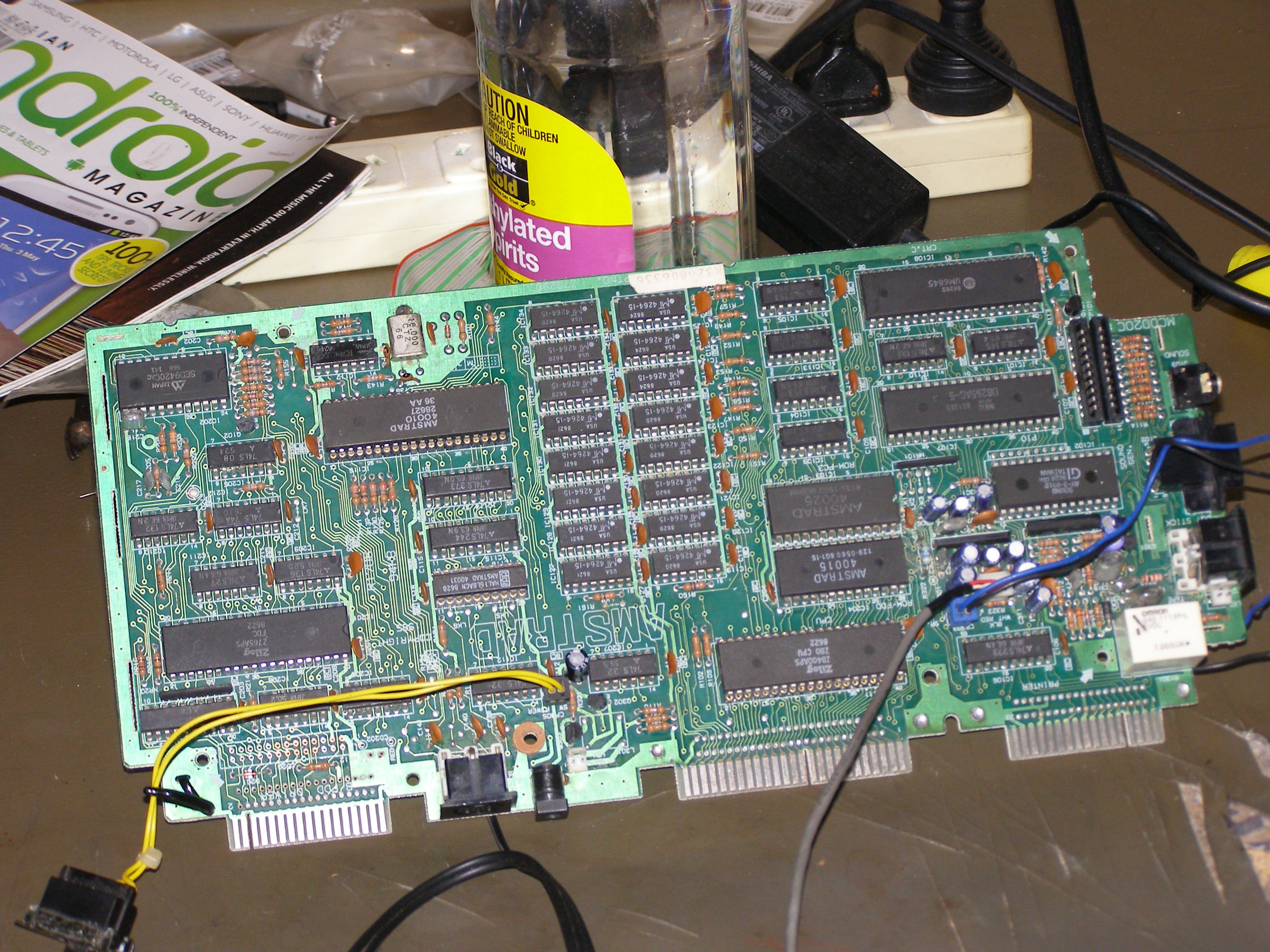
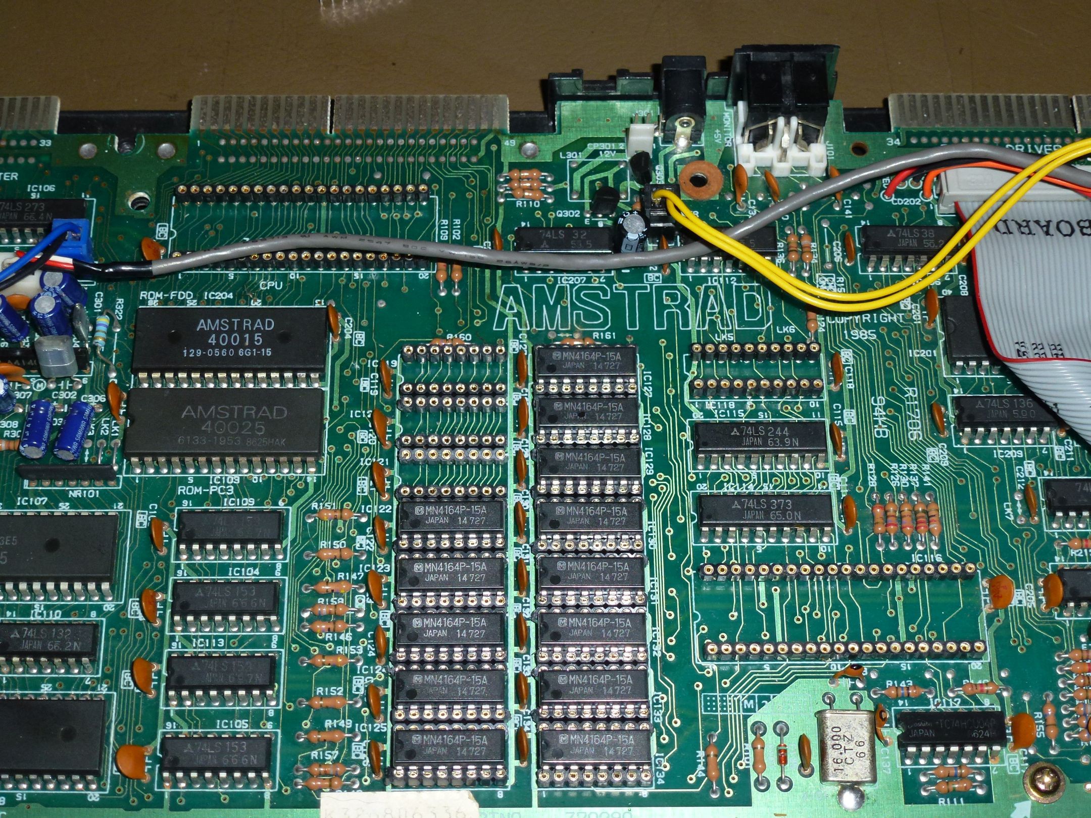
This picture was taken after some sockets were replaced.
It shows the the basic design. The major parts being, Z80 CPU, ROMs, DRAM, Sound Chip, ASIC for video, Gate Array for memory bank switching, 6845CRTC for video timing, 8255 for interface and a FDC765 to control the floppy drive.
The first thing I did was to remove the socketed chips, CPU, ASIC and gate array.
I noticed this ...

... a rather dirty looking socket.
So I replaced the three sockets but to no avail. The problem persisted.
I then replaced the CPU as I had another lying around. No joy there either.
Time to order parts.
Here are the three socketed chips ...
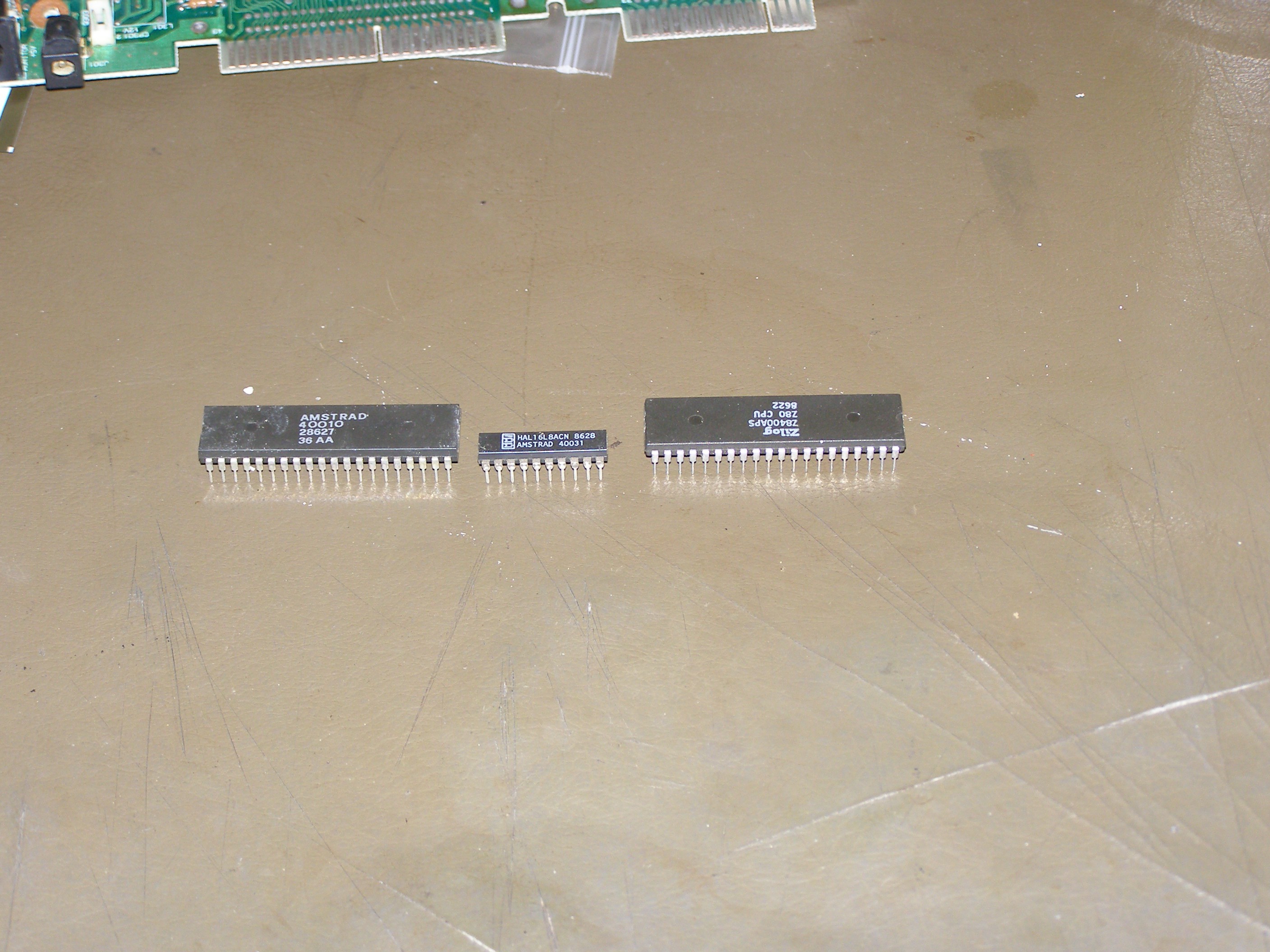
They are, ASIC, gate array (HAL) and CPU.
The CPU is run of the mill and a compatible version is still in production today.
The ASIC is mask programmed in the factory so I expected that I would have no hope of finding that.
The gate array (HAL) has a programmable counterpart (PAL) but I very much doubted I could find the original code and I don't have a programmer for this type of chip anyway.
After looking around the net I was astounded to find a brand new, in the packaging, made in the 1980's, for this computer - ASIC. This is the chip that I though I would never find so I was going to order it even if it's not the cause of the problem.
Even though my main suspects were faulty RAM or a corrupted ROM, I ordered the following.
An ASIC because I wasn't going to miss the chance.
I ordered the CPU as they're cheap and easy to find.
I ordered the 6845CRTC because it is getting rare to find.
I also ordered a logic probe because I am on budget (you'll laugh) ...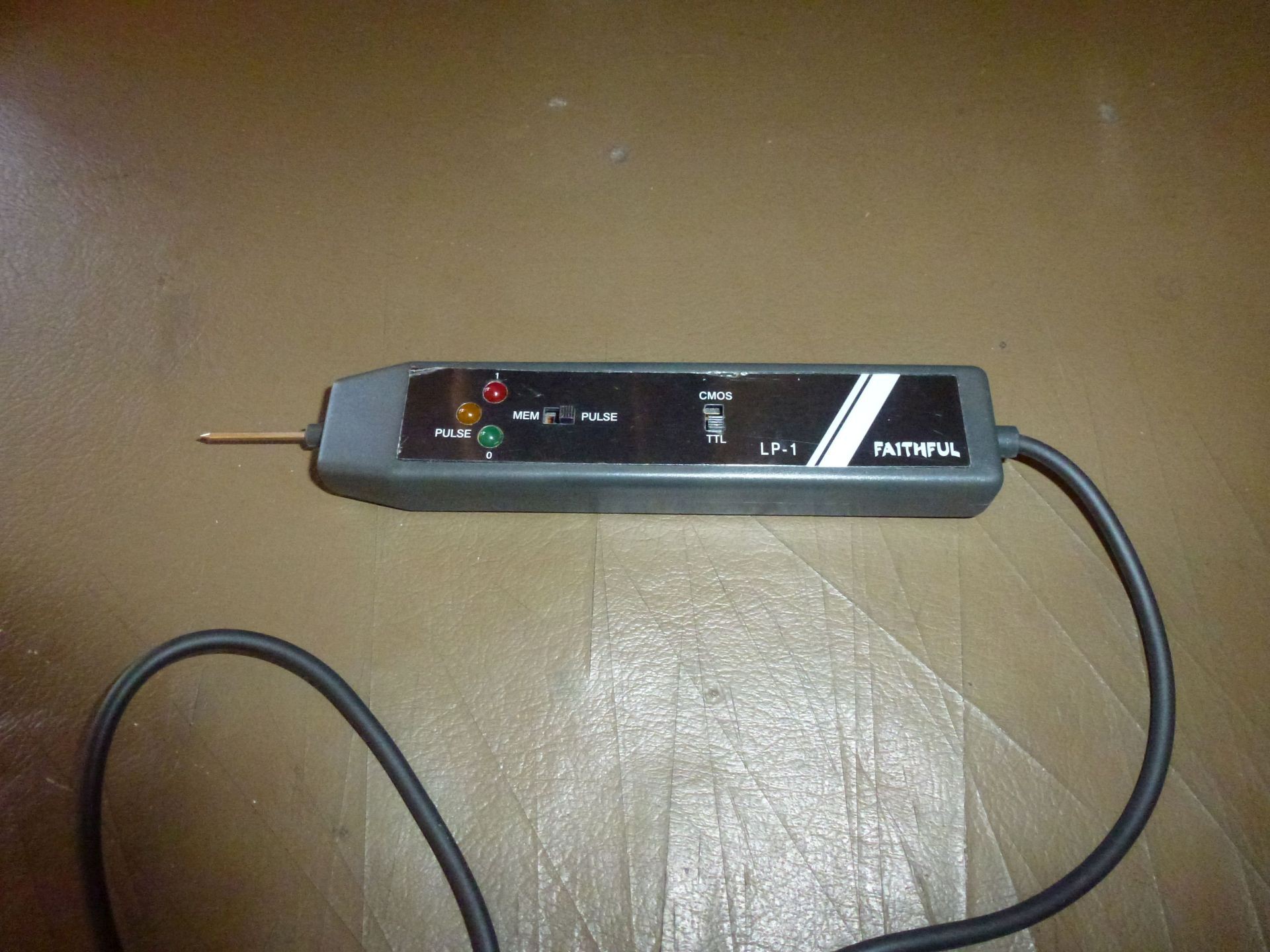
When I received the parts, I replaced the CPU and ASIC. No joy once again but I expected that.
I had one of these computers when I was younger so I had a basic understanding of how they worked.
With some google fu I found a disassembly of the ROMs. The CPU loads up all the registers in the CRTC and gate array and then copies some ROM to RAM before jumping to the RAM that has been copied to. It seemed to me that it was something going wrong with this copy process or immediately after because the CPU was getting to the point where the registers were setup.
I did some probing around with my logic probe looking for a stuck bit on the address or data bus. I found some things that seemed a little odd but nothing concrete.
I then looked around the control lines and found very odd behavior on the interrupt (INT) pin but I couldn't really make any definite conclusion about this.
Well as my main suspicion was RAM or ROMs I decided to order RAM as I don't have a programmer for the ROMs. I really didn't want to replace the RAM as there are 16 chips with 16 pins each. De-soldering 256 pins, what fun.
I ordered RAM and sockets. When it arrived I tried an old trick with faulty RAM.
If you piggy back a new RAM chip over a faulty RAM then often the fault will disappear but not always. Unfortunately, sometimes you will end up damaging the new RAM that you are using to test with. With cheap ram it's worth a try as replacing soldered in RAM chips can take a long time.
No joy yet again with the RAM test trick.
Ok, now it's unavoidable, I have to desolder 256 pins.
This was an issue for me! I have been away from electronics for about 20 years and in that time my HQ vision has dropped to below HQVGA.
When I was replacing the first three sockets I couldn't see what I was doing. I was remembering and going though the motions after which I took a pic to zoom on the PC so I could see how I went.
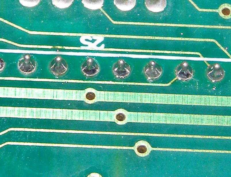
As you can see, I did atrociously. Not using enough solder and leaving gaping holes in the solder joints.
I touched these joints up and took another pic and they were acceptable.
At this point I realized that I need to make an active scope (motion macro camera with screen) for the bench so that I can see what I am doing. Unfortunately I won't have the time or the money to do so while I am repairing this computer.
I started desoldering the RAM by desoldering the pins of a chip and then removing it.
I had only removed 3 chips this way before I lifted a track off the circuit board.
I used to use a jewelers screwdriver to flick a desoldered pin back and forth to see if it's free (completely desoldered). Now because I can't see the pins I have to go by feel and that is obviously not good enough.
Plan B!
I went and bought some fine point wire cutters and cut the legs off of the RAM chips while there still soldered into the board. Once I had removed all the chips from their pin, I then removed all the pins one by one.
Then I had to repair the broken track, put in sockets and then new RAM.
I then put it all back to together to try it again.
I turned it on expecting to here the beep sound these computers made when you switched them on.
No beep sound ... but hey everything else is working. Turns out that the speaker was also faulty.
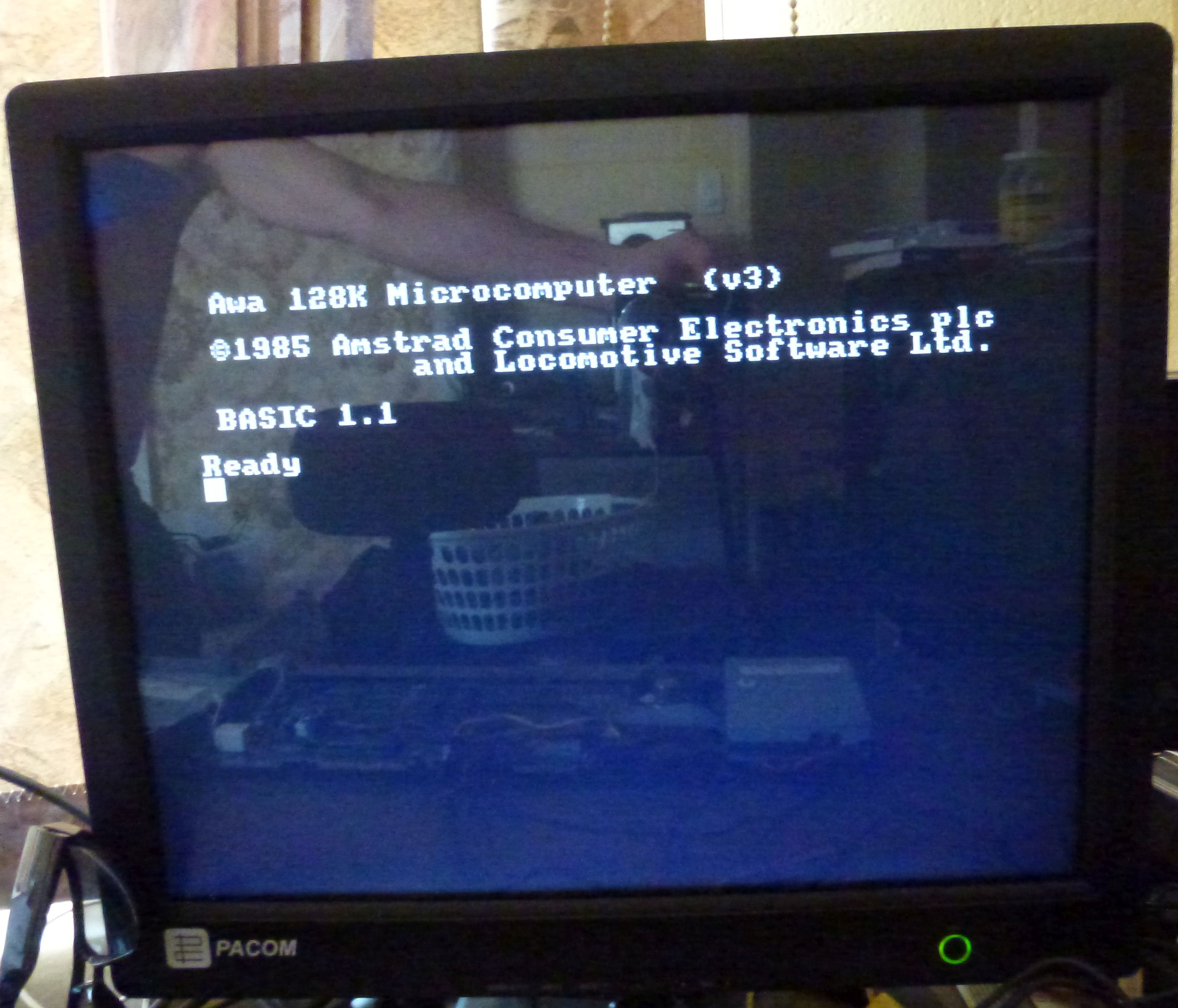
Above, the screen is just monochrome, I have to make another hack for color.
And here is the first (actual) hack ...
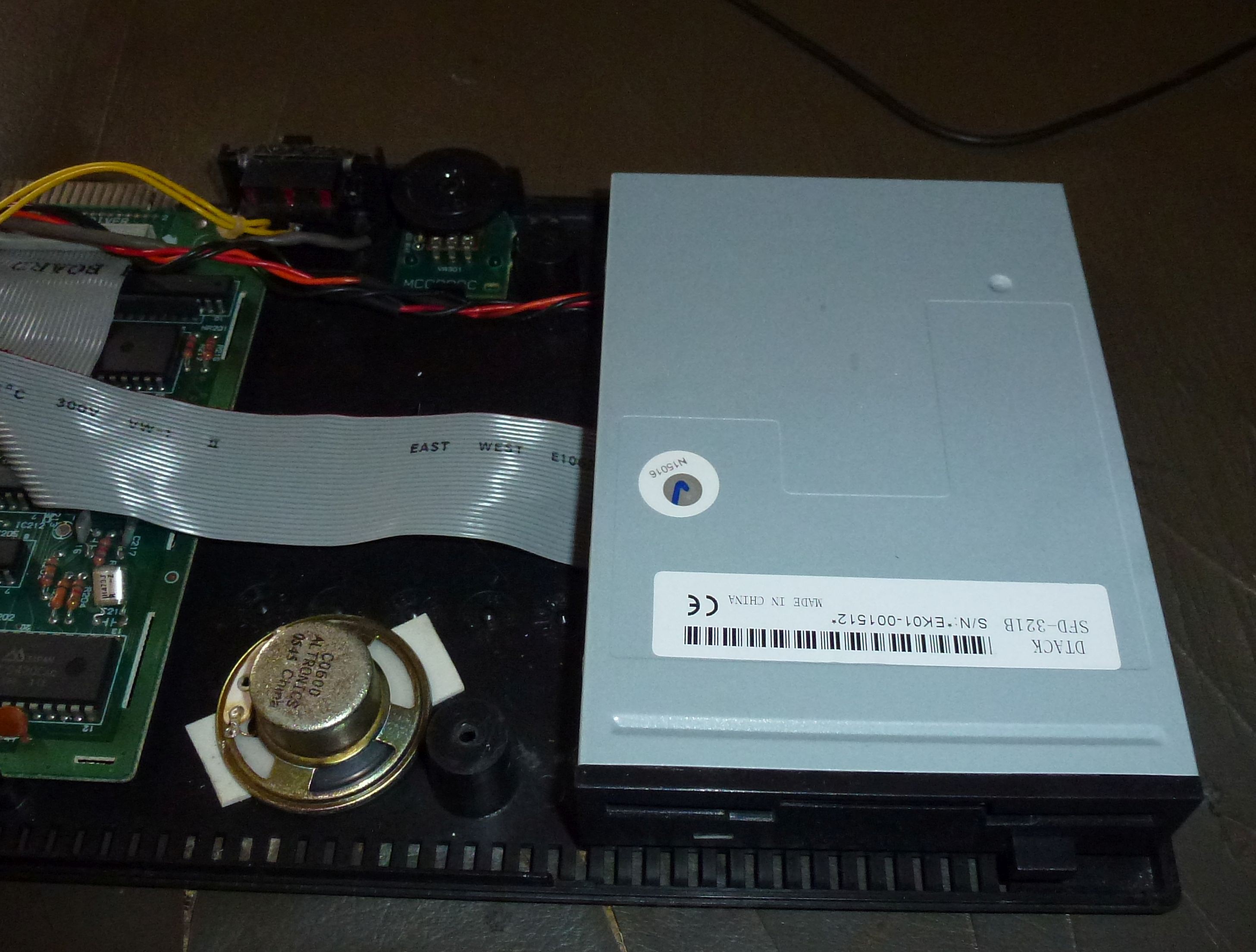
I removed the 3 inch FDD and installed a 3.5 inch FDD because I can't buy 3 inch disks anymore.
The hardest part of this hack was getting CP/M and data onto the 3.5 inch disks.
The only supported floppy format (from memory) is 40 track, 9 sectors per track, 512 bytes per sector and single sided (not PC compatible).
The computer doesn't have the ability to format a disk in ROM. ie A disk format utility must be be loaded from disk. Catch 22 lol.
I had to revive a PC that was so old that it had the floppy controller chip built into the main board so that the floppy controller registers could be accessed directly to generate the non-compatible format.
It went like this ...
Put enough bits together to make an ancient PC.
Turn on power.
Power supply explodes.
Replace power supply.
Turn on power.
Smoke comes from CPU.
Replace CPU.
... You get the picture lol.
The next hack in this theme will be color display. The Amstrad CPC6128 has color but I need to convert the output to something a modern monitor will display.