 will.sweatman
Parts -
3D printer source files from dragonator.
4D Systems 4.3 inch touch display (datasheet) (programmer).
8 gig micro SD card.
Adafruit PowerBoost 500 charger/booster (datasheet).
Lipo 2500mAh 3.7v battery.
USB breakout board.
10 Position rotary switch.
3 orange LED's (Radio Shack).
1 red LED (Radio Shack).
1-10k resistor (Radio Shack).
2-220ohm resistors (Radio Shack).
The Build
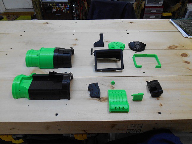
It all started with the dragonator's files. I simply downloaded and printed them. I used two different colors because I wanted to test each printer head, as it was a new printer. In hindsight, I would have kept it all black. Also, the friend I'm making it for will be doing the painting and touching up the finer details and minor imperfections with some type of putty.
Mounting the Display
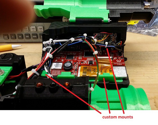
This was somewhat annoying because the mounting tabs for the display were only slightly off. I had to break the tabs off and make custom mounts to hold it in place. If anyone tries to replicate my work, I would not recommend mounting the display the way I did. In the Mark 2, the mounts will be much better.
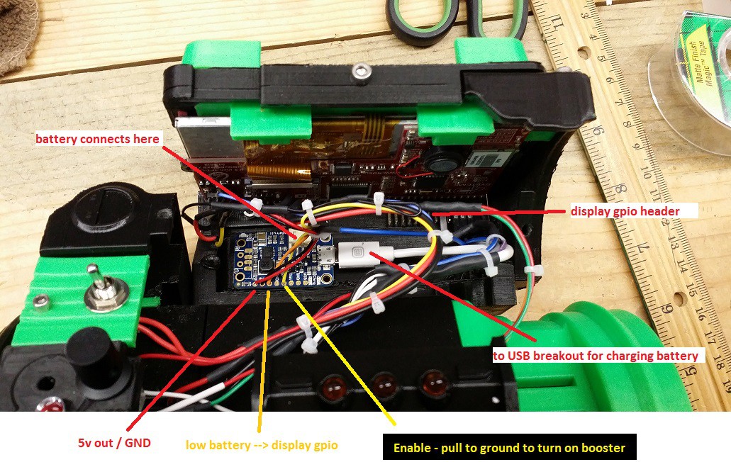
The Power Circuit
The Adafruit power circuit serves four purposes:
- To convert the 3.7 volts from the battery to 5v for the display.
- To provide a charging circuit for the battery.
- To provide a way to power the device on/off without the need for a high current switch.
- To give the operator a warning when the battery is low.
That little board of theirs does all four of these things.
- The display pulls about 250mA at 5v, so the battery will last ~10hours on a single charge.
- All I have to do is pull the EN pin low, and this will shut the booster off. Meaning any type of switch can be used to power the Pipboy On and Off (I wound up using a switch FAR larger than I needed. This will change in the Mark 2).
- There is a LB pin that will go low when the battery drops below 3.3 volts. This triggers the display to throw a "low battery" warning screen.
Programming the Display
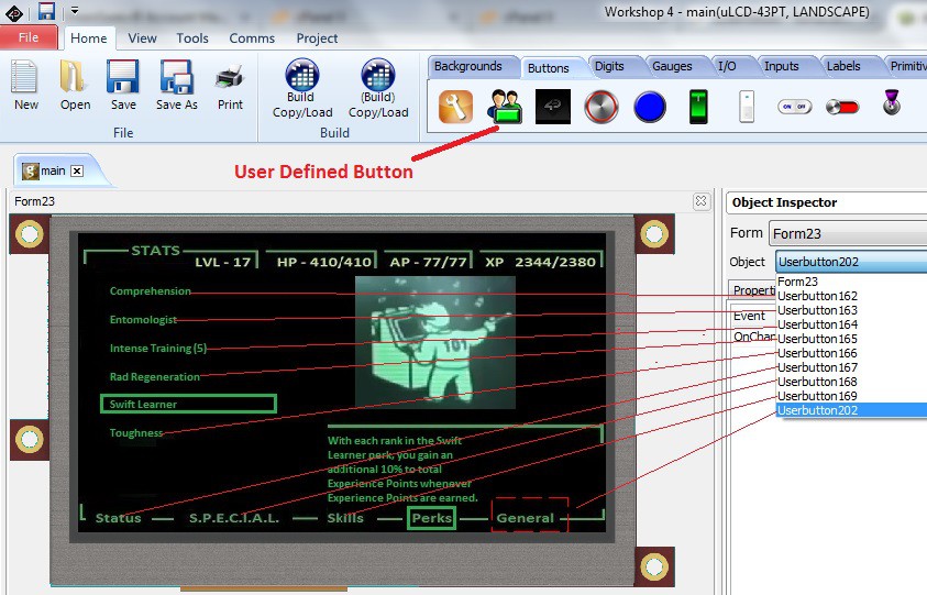
The 4D Systems 4.3 "Intelligent" display is programmed with the free Workshop 4 IDE. This program gives you four different options to use - one of them being the Visi Genie. This is a WYSIWYG programming interface, and the one I chose to use. I wanted to see how far I could take this project without using any code - the idea being that someone with only a very limited amount of electronic experience could replicate my project.
That's right. I did not have to write a single line of code for this project.
Each image that is painted onto the display is called a "Form", and you can make as many Forms as you want. Each screen was made in MS Paint and loaded into the Form as a JPG image.
I used this video to grab screenshots of the many different Pipboy avatars. Then I used the "User Defined Button" option to make buttons out of areas on the screen. This allowed me to make a button out of the area around "RADS", "S.P.E.C.I.A.L.", and all the other 'button' areas of the JPG images.
The IDE allows each User Defined Button only one action. The one I chose just loads a particular Form. So if the user presses the area around RADS, the RADS Form gets painted onto the display.
It should be noted that this method is not optimal, but necessary in order to avoid code and a separate microcontroller. For instance, each Form has many different buttons, all mapped to other Forms. The result was slightly over 200 User Defined Buttons. These ate up the limited memory on the display, and prevented me from making any other Forms. :-(
If I was making this from scratch again, I would make a single Form with several buttons, and then make a "Home" button for each of the screens that led back to that Form.
Display GPIO
The 4D Systems display has 5 GPIO pins that can be accessed from the IDE. The way they work is straight forward. You load an input or output 'tack' into Form 0, and then link it to a single action. For the Low Battery screen, all I did was link an input tack to load the Form that had the Low Battery image on it. Attached to the input...
Read more »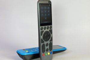
 Max.K
Max.K
 Dominic Buchstaller
 Tony E. Nazzal
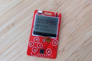
 deʃhipu