 Brandon Piner
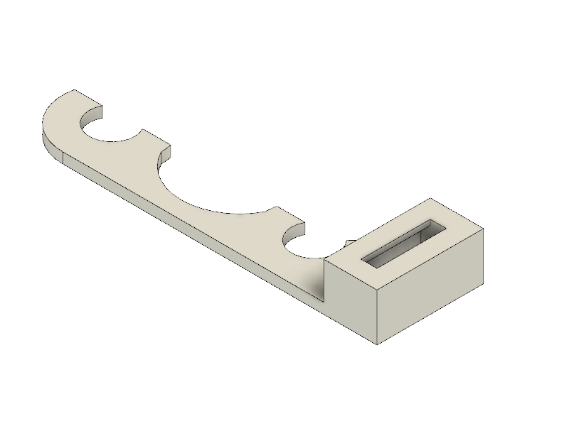
The core of this project is the mounting bracket that allows anyone to create their own mounts.
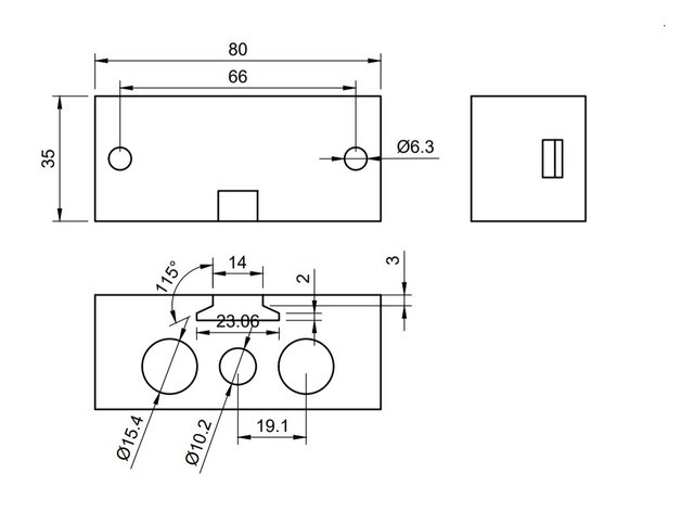
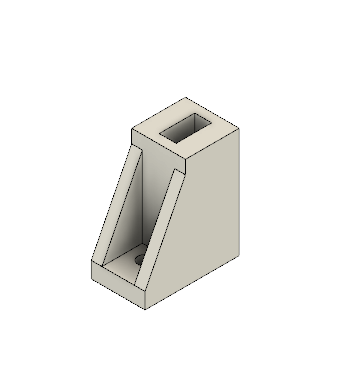
The dimensions of the bracket are shown below so that anyone can use it as a starting point when designing their mounts.
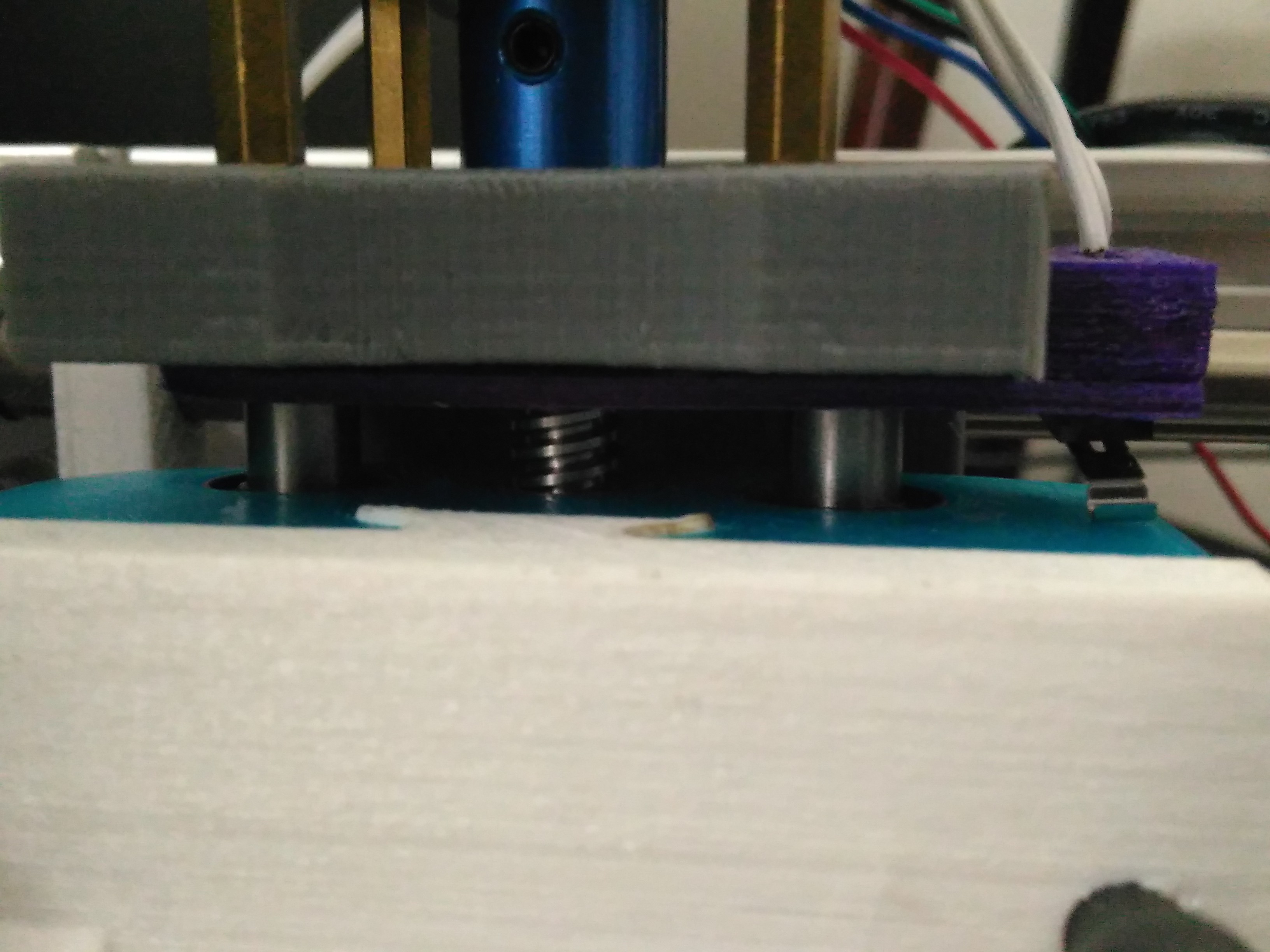
The idea behind having a slot in the mounting bracket is to have all your tools at a known z-height. This probably does not get rid of the final z-height tuning but it will assist in the approximate height. For instance you should not have to adjust your laser again!
I have also made some parts that help protect the machine from the following common mistakes (my mistakes at least):
- Crashing the bed and/or head into the frame by telling it to go beyond its limits
- Crashing the tool into the bed by lowering it too much
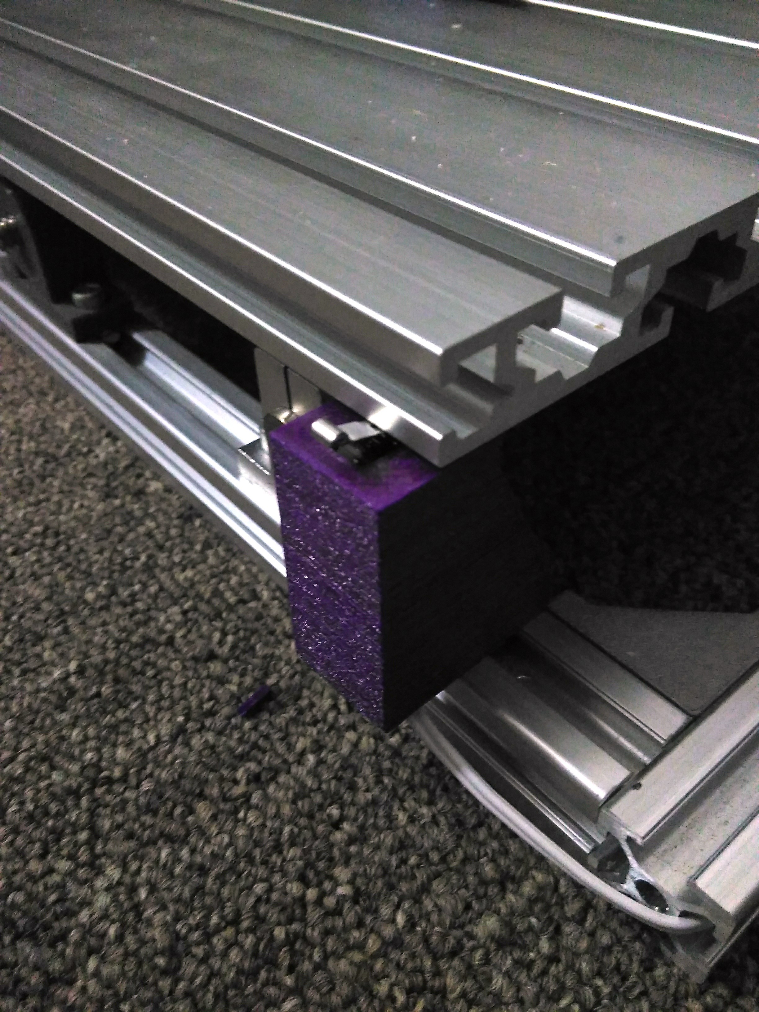
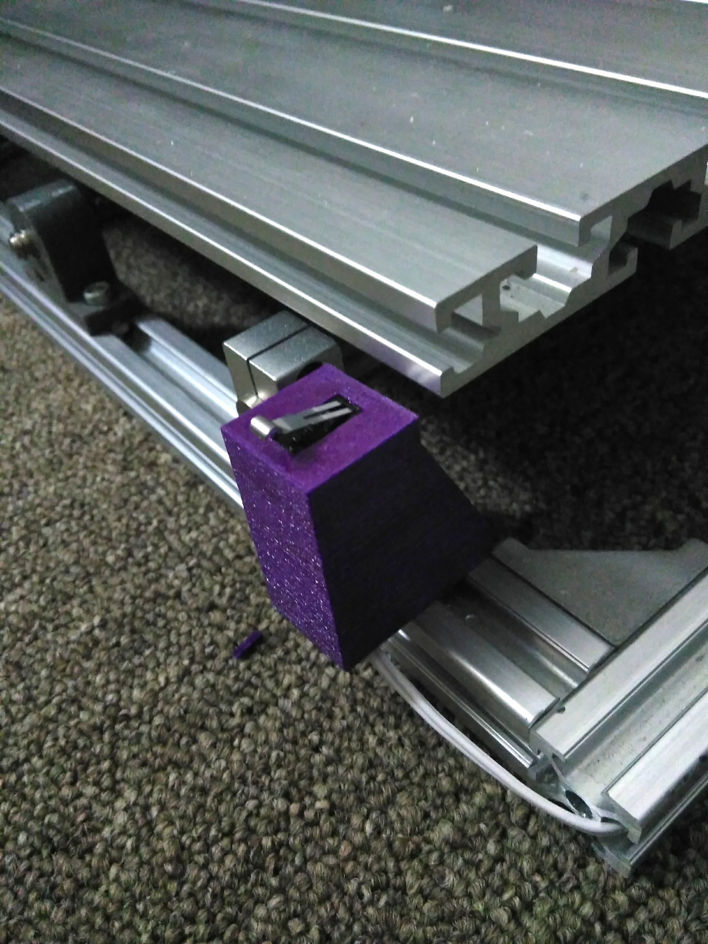
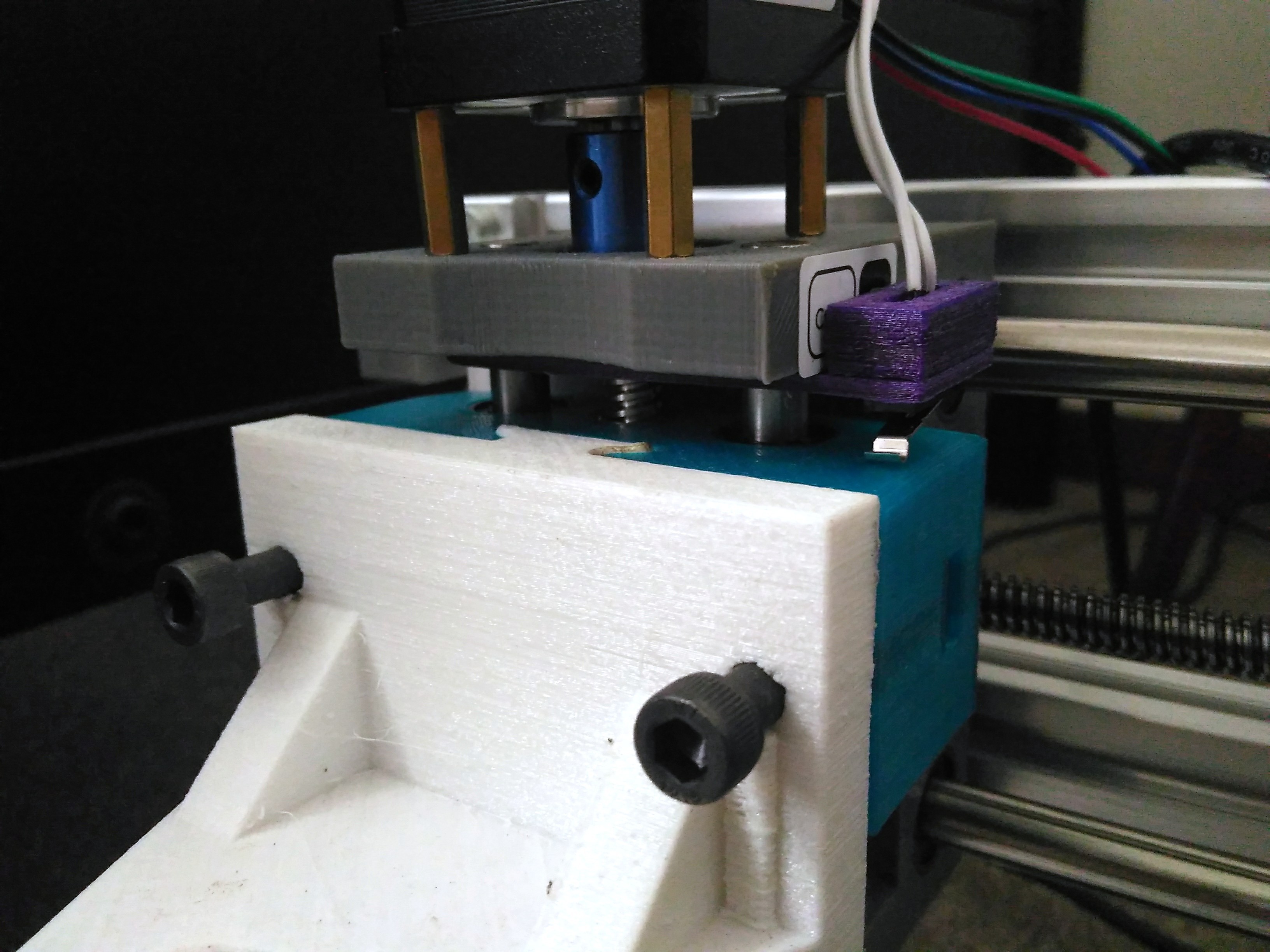
To solve the above issues I made limit switch end stops. I had to change some settings on the GRBL controller which implements soft limits.
To install the limit switches:
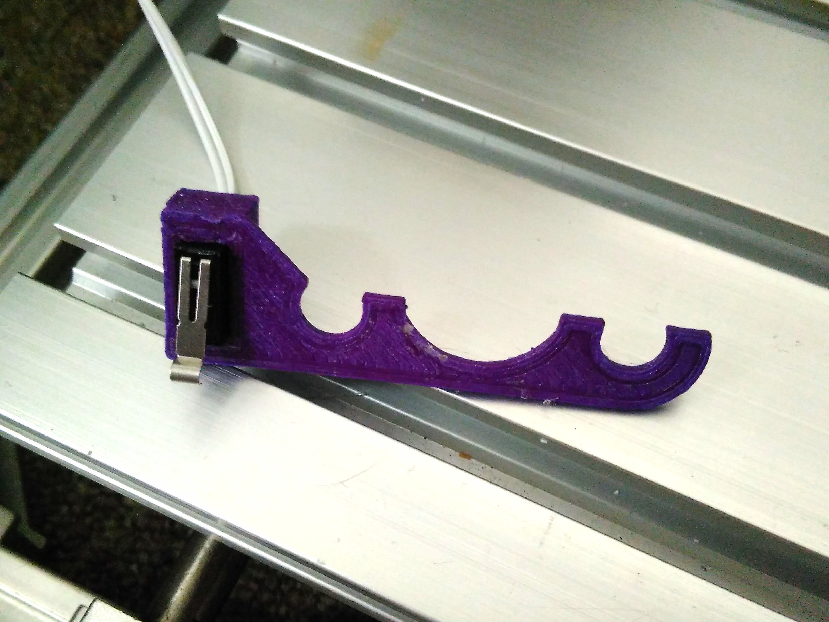
- 3D print the X End Stop, Y End Stop and Z End Stop. I printed it all PETG and 0.2 mm layer height. This allowed a slight amount of flexibility to snap the end stops on the machine
- Insert the limit switches (size is 13 mm x 6 mm L x W) into their respective end stop
- Snap the z and x end stops into place. The y end stop requires one of the bolts and T type nut fasteners.
- Follow the GRBL guide on wiring the limit switches. I have a woodpecker like board so I used those instructions. https://github.com/gnea/grbl/wiki/Wiring-Limit-Switches
- Set up the homing cycles https://github.com/gnea/grbl/wiki/Set-up-the-Homing-Cycle
- Do not forget to set the GRBL $130, $131 and $132 which specify how large your CNC work area is
- Enable soft limits which stops the machine moving further than the work area. https://github.com/gnea/grbl/wiki/Grbl-v1.1-Configuration#20---soft-limits-boolean
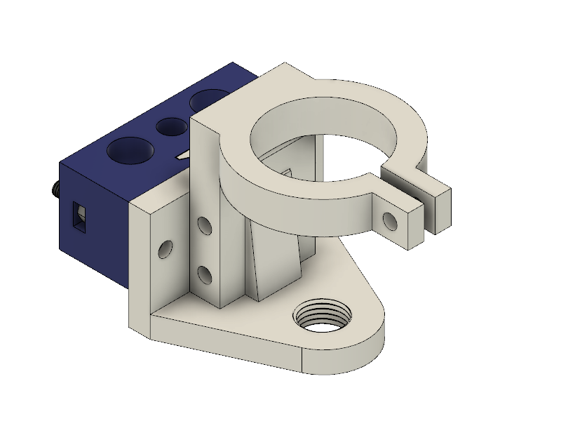
To install the Z mounting bracket:
- 3D print the Z mounting bracket
- Remove the original Z spindle/laser holder by first unscrewing the stepper motor. Then unscrew the lead screw from the spindle holder
- Push the bearing rods out until you can remove the spindle holder.
- Push the bearings and the brass thread out of the original z mount and put them into the new printed mount.
- Reverse step 1 and 2 to install the new z mounting bracket.
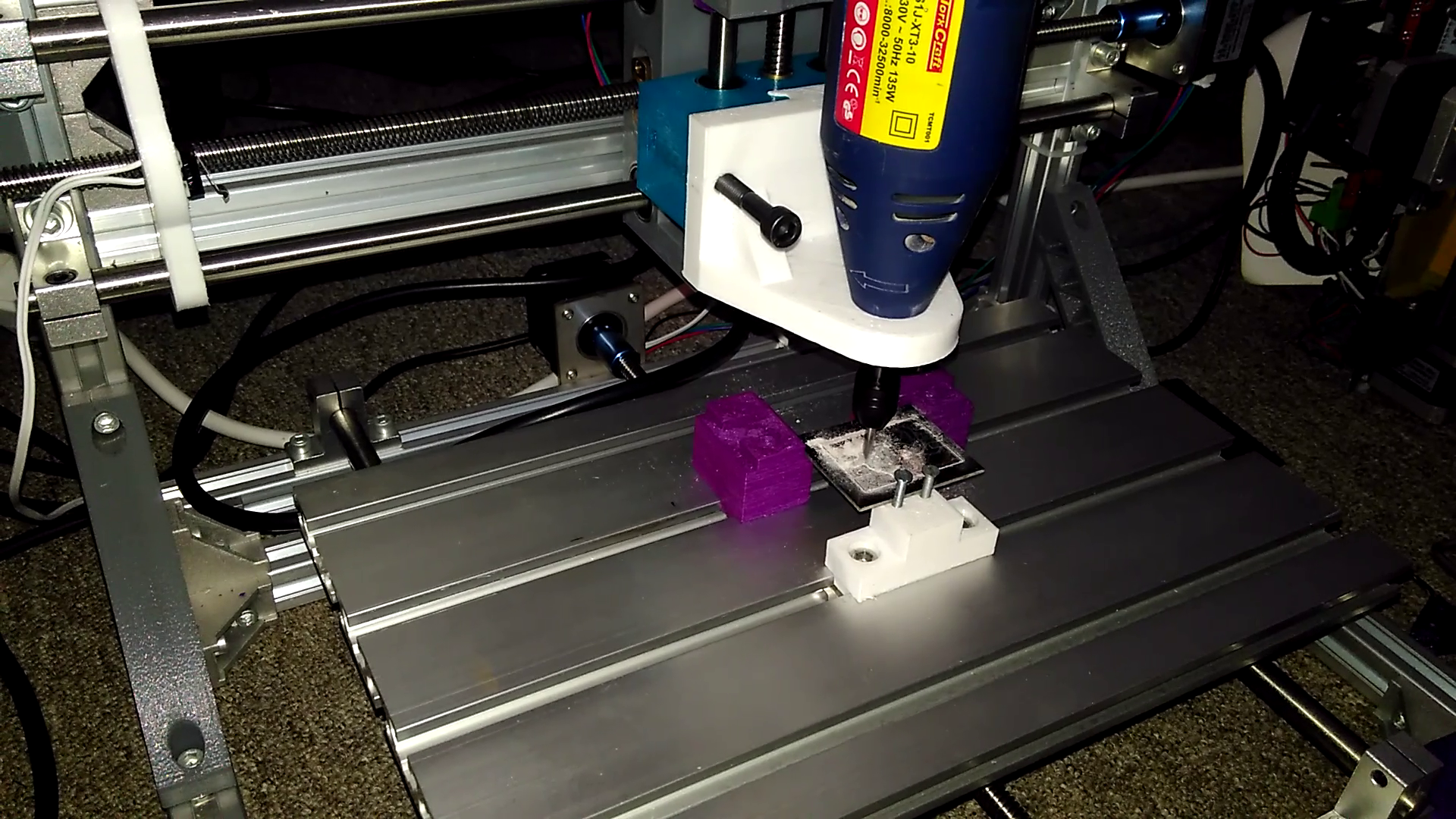
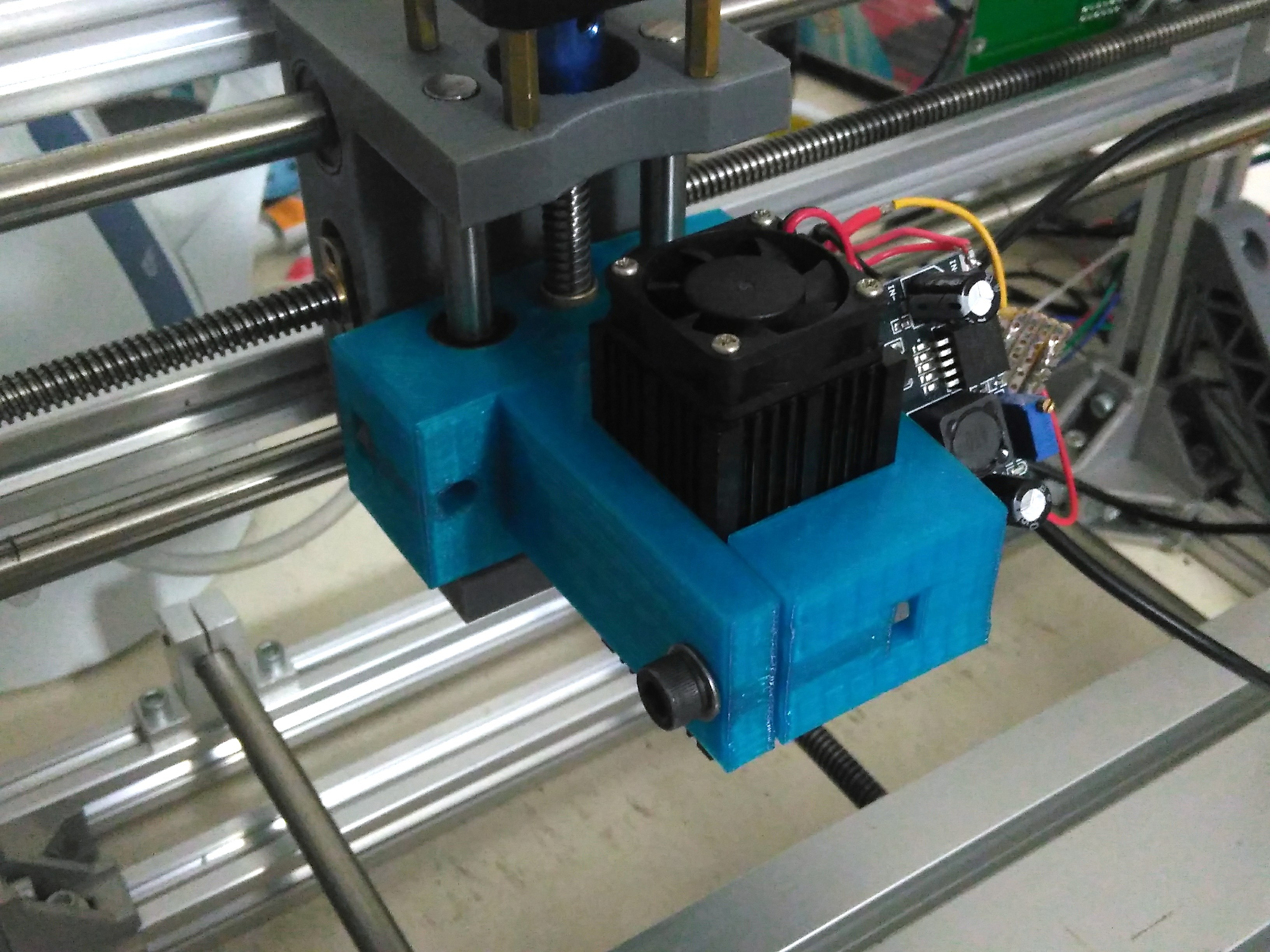
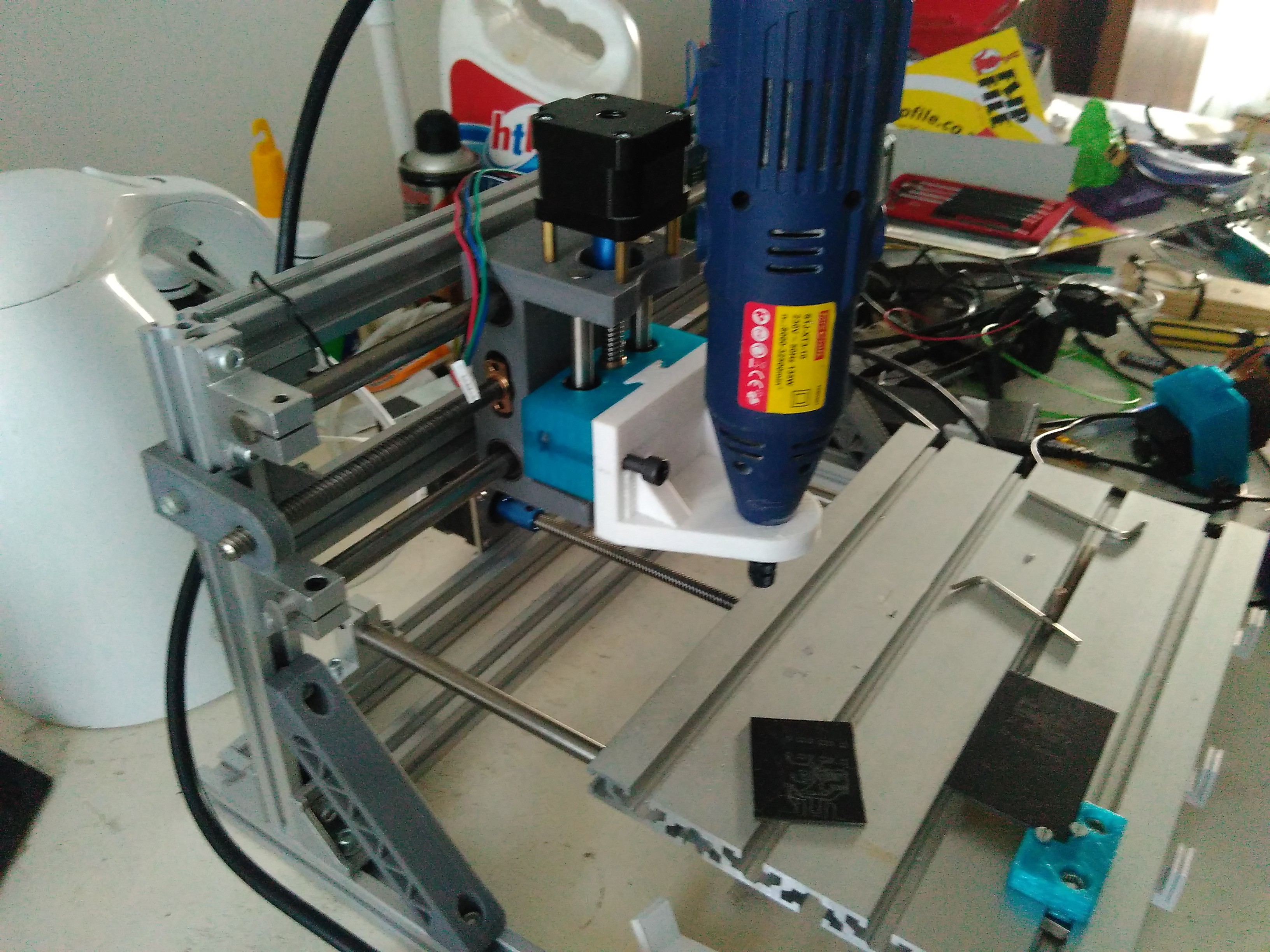
Now you can install the laser or rotary tool by sliding it into the newly installed z-mount!
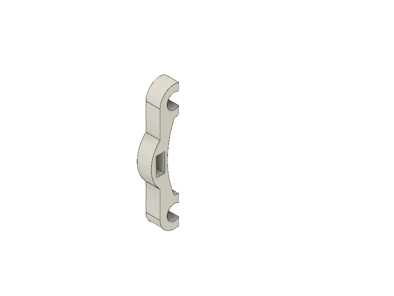
Designing custom mount:
If you need to make a mount for a different tool or a rotary tool then you should use the drawing below as a guide for the sizes. Don't forget to add tolerances!


 Myles Eftos
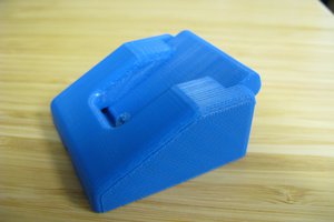
 Alex Rich
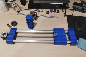
 Elliot
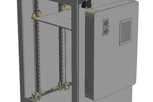
 Patrick
Question. What is the diameter of the tool holder strap on the Tork Craft Top Mount file? I am looking for something to hold the original DC motor spindle on an old 2418.